
Technical data


D-2 CommandTouch User’s Handbook
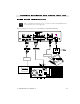
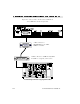
1 Locate the AXB-EM232 Enhanced Master box and rack mount assembly.
2 Locate the cable labeled FG11-027. There will be a 4-pin captive compression style
connector on each end of the cable. Connect one end to the port labeled “AXlink,” located on
the back panel of the AXB-EM232 Enhanced Master box.
3 Locate the cable labeled “605-1344-01.” One end will have a 6-pin captive compression-
style connector. Plug this end into the 6-pin port labeled “RS232” on the back panel of the
AXB-EM232 Enhanced Master box.
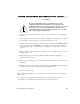
4 Locate the cable labeled
“605-1387-01.” One end
will have an 8-pin captive
compression-style
connector. Plug this into
the port labeled “RS232/
422” on the back panel of
the AXB-EM232
Enhanced Master box.
5 Locate the PS2.8 power supply. Plug the power supply’s green 2-pin connector into the port
labeled “PWR” on the backpanel of the AXB-EM232 Enhanced Master box.
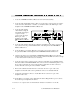
6 Open the rear cabinet door and install the AXB-EM232 Enhanced Master box and rack
mount assembly in the first rack position below the cabinet shelf. (Make sure there is enough
room for all four rack mount screws to be installed.)
7 Locate the end of the FG11-027 cable. This connects to the touch panel. On the back side of
the touch panel, you will find a door flap. Inside there are three connectors. Connect the
FG11-027 cable to the 4-pin connector labeled “AXlink.”
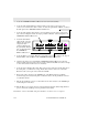
8 Remove the cable connected to the TABLET port on the EnterpriseSerie
Leadership
Conferencing System (LCS) back panel. Connect this cable to the 25-pin RS232 connector
on cable 605-1344-01.
9 Take the 25-pin RS232 connector on cable 605-1387-01 and connect it to the TABLET port
on the back panel of the LCS.
10 Take the PS2.8 power supply and set it on the shelf inside the LCS cabinet. Plug the PS2.8
power cord into the switched power strip inside the LCS cabinet.
Installation of the CommandTouch panel hardware on the LC is now complete.