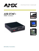
instruction manual AXB-DTMF+ DTMF+ Interface AXlink Bus Controllers
AMX Limited Warranty and Disclaimer AMX Corporation warrants its products to be free of defects in material and workmanship under normal use for three (3) years from the date of purchase from AMX Corporation, with the following exceptions: • Electroluminescent and LCD Control Panels are warranted for three (3) years, except for the display and touch overlay components that are warranted for a period of one (1) year.
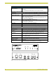
Table of Contents Table of Contents Product Information .................................................................................................1 Specifications .................................................................................................................... 1 Configuration and Installation .................................................................................3 Setting the Internal Jumpers ..............................................................................
Table of Contents ii AXB-DTMF+ DTMF+ Interface
Product Information Product Information The AXB-DTMF+ DTMF Interface (FIG. 1) links an Axcess central controller to a telephone network, enabling dual tone multi-frequency (DTMF) and audio pass-through control. The AXBDTMF+, with a programmed central controller, processes incoming calls and initiates outgoing calls to any pager or cellular phone. The multi-function AXB-DTMF+ can be integrated for many imaginative and creative purposes within a home or work environment using touch-tone control.
Product Information AXB-DTMF+ Specifications (Cont.) Operation modes (set via internal jumpers): • Auto Answer • Line Type Refer to Setting the Internal Jumpers section on page 3 for details. Front panel components (FIG. 1): AXlink LED Blinks on and off to indicate that the AXB-DTMF+ is communicating with the central controller. Off Hook Phone LED Lights when ever a telephone connected to the PHONE connector on the AXBDTMF+ is in an off-hook condition.
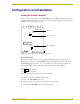
Configuration and Installation Configuration and Installation Setting the Internal Jumpers There are two 2-position jumpers on the AXB-DTMF+ circuit card (FIG. 1). Each jumper is set to a default pin setting. These jumpers are positioned to enable automatic call answering and select line setting for a leased line or phone operation. Audio In pot JP1 JP1 - Line selection JP2 JP2 - Auto Answer front FIG. 1 Location of JP1, JP2 jumpers, and Audio In potentiometer.
Configuration and Installation Line Setting mode The 2-position jumper JP1 selects PHONE or LEASED line operation when system powers on. FIG. 3 shows the default setting. pin 3 pin 2 pin 1 Phone Leased FIG. 3 Line Setting jumper JP1 (default setting = PHONE) To change the line setting default from PHONE to LEASED: 1. Remove the AXB-DTMF+ cover from the unit housing. 2. Remove the jumper from pins 2 and 3, and place it on pins 1 and 2. 3. Re-install the AXB-DTMF+ cover onto the unit housing.
Configuration and Installation Connecting External Telephone Lines Telephone cabling for both the input and extension lines are standard RJ-11 type connections. Follow these steps to connect external telephone lines. Cables and connectors for telephone and audio hook-up are not included with the AXB-DTMF+. 1. Check the circuit card jumper settings to match line type and auto answer mode. For more information, refer to AXB-DTMF+ Jumpers in the Pre-Installation section of this manual. 2.
Configuration and Installation Testing the AXB-DTMF+ Follow these steps to test the AXB-DTMF+: 1. Disconnect AXlink power. 2. Remove the cover from the unit housing and set the AUTO ANSWER jumper to AUTO ANSWER ON then reinstall the cover on the unit housing. 3. Reconnect AXlink power. The status LEDs should blink in sequence from right to left and the AXlink green LED should be blinking. 4. Place a call to the AXB-DTMF+ from an outside line. 5. The RING LED should light with an incoming ring. 6.
Programming Programming Program the AXB-DTMF+ to send outbound DTMF codes using Axcess Send_Commands from the control Fine Tuning - commands allowing experienced users the ability to obtain performance in adverse system. Use the commands described in this section with the Axcess Programming Guide to program the AXB-DTMF+. The Send_Commands are divided into the following categories: ! Operative: normal day-to-day commands controlling the overall operation of the AXBDTMF+.
Programming Operative System Send_Commands (Cont.) Command Description AUDIO-ON Enable audio from passing through the AXB-DTMF+ to the phone line. Default at reset = YES (for backwards compatibility) Example: SEND_COMMAND DTMF, 'AUDIO-ON' Enables the audio from passing through the AXB-DTMF+ to the phone line. AUDOUT-OFF Disable audio from passing from the phone line to the audio out output of the AXB-DTMF+.
Programming Operative System Send_Commands (Cont.) Command Description DIAL-X-XXX-XXXX Dial number and send DTMF. • Spaces or hyphens are ignored when dialing. • A 'W' in the dial command will cause the AXB-DTMF+ to wait for dial tone before dialing the next digit in the dial command. The wait will time out after 2 seconds. If a time out occurs, the AXB-DTMF+ will indicate this by sending a push and release on channel 45.
Programming Operative System Send_Commands (Cont.) Command Description ON HOOK Place AXB-DTMF+ on hook. Default at reset = YES Example: SEND_COMMAND DTMF, 'ON HOOK' Places the AXB-DTMF+ on hook. Timing System Send_Commands The following table lists the commands, which establish normal signal timing. Changing default time values may inadvertently alter the operation of the AXBDTMF+. It is unnecessary to change most default values.
Programming Timing System Send_Commands (Cont.) Command Description LOSSLCMIN-XXX The minimum time a loop current is off (used to detect other end hung up). • Time increment = 10 ms • Default at reset = 10 Example: SEND_COMMAND DTMF, 'LOSSLCMIN-15' Sets a .15 second (150 ms) minimum off time for a loop current. OBUOFFMAX-XXX Outgoing busy off time maximum. • Time increment = 10 ms • Default at reset = 60 Example: SEND_COMMAND DTMF, 'OBUOFFMAX-65' Sets the outgoing busy off time maximum to .
Programming Timing System Send_Commands (Cont.) Command Description OREOFFMAX-XXX Outgoing reorder (fast busy) off time maximum. • Time increment = 10 ms • Default at reset = 35 Example: SEND_COMMAND DTMF, 'OREOFFMAX-45' Sets the outgoing reorder (fast busy) off time maximum to .45 second (450 ms) (see NOTE for Send_Command 'OBUOFFMAX-XXX ').
Programming Timing System Send_Commands (Cont.) Command Description ORIONMAX-XXX Outgoing ring on time maximum. • Time increment = 100 ms • Default at reset = 22 Example: SEND_COMMAND DTMF, 'ORIONMAX-30' Sets the outgoing ring on time maximum to 3.0 seconds (30,000 ms) (see NOTE for Send_Command 'OBUOFFMAX-XXX'). ORIONMIN-XXX Outgoing ring on time minimum. • Time increment = 100ms • Default at reset = 8 Example: SEND_COMMAND DTMF, 'ORIONMIN-25' Sets the outgoing ring on time minimum to 2.
Programming Timing System Send_Commands (Cont.) Command Description TONE TIME-XXX Set length of each generated tone and time between tones in the Dial Send_Command (refer to 'DIAL-X-XXX-XXXX') • Time increment = 1 ms • Default at reset = 100 ms Example: SEND_COMMAND DTMF, 'TONE TIME-100' Sets tone time length to .11 second (110 ms). Fine Tuning Send_Commands The following table lists the commands that fine tune AXB-DTMF+ signal timing. Most likely, you will not have to change Fine Tuning parameters.
Programming Distinctive Ring Patterns and Send_Commands Distinctive ringing is a service provided by the local telephone company. Distinctive ring allows additional phone numbers to be assigned to a single phone line. Then, depending upon the number dialed, the ringing pattern is different. The AXB-DTMF+ can identify up to four distinctive ring default patterns. Default time values for each pattern are shown in FIG. 1. A pattern consists of five parts.
Programming Changing a Default Ring Pattern Change a default ring pattern using the appropriate Send_Command when programming the AXBDTMF+. Each ring pattern consists of five parts with each part having a specific Send_Command. For more information on distinctive ring Send_Commands, refer to Distinctive Ring Send_Commands. Example: Pattern 4's five parts are as follows: ! Part 1 is high and 300 ms (.3 seconds) long (ring). ! Part 2 is low and 200 ms (.2 seconds) long (no ring).
Programming Distinctive Ring Send_Commands The following Send_Commands are available for changing the default distinctive ring patterns. Each ring pattern consists of five parts with each part requiring a Send_Command. Distinctive ring Send_Commands produce four patterns (P1 through P5) and high and low time values (_X). Refer to FIG. 1 on page 15 to see the timing diagram based on defaults at start-up/ reset.
Programming Distinctive Ring Send_Commands (Cont.) Command Description PY_Z-XXX The remaining Ring Patterns and Parts Send_Commands are used just like the examples shown for Pattern 1 above. Refer to Figure 12 and the following information.
Programming (* CONSTANT DEFINITIONS GO BELOW *) (*********************************************************************) DEFINE_CONSTANT (*********************************************************************) (* VARIABLE DEFINITIONS GO BELOW *) (*********************************************************************) DEFINE_VARIABLE STATE (* STATE OF THE SOFTWARE "STATE MACHINE" BUSY_COUNT (* NUMBER OF RETRIES *) *) (*********************************************************************) (* LATCH
Programming IF(STATE=2) { STATE=3 SEND_COMMAND DTMF_CARD,'OFF-HOOK' WAIT 20 'WAIT FOR DIAL TONE' { SEND_STRING 0,"'ERROR: NO DIAL TONE',13,10" SEND_COMMAND DTMF_CARD,'ON HOOK' STATE=255 } } (***********************************************************************) (* IF DIAL TONE IS RECEIVED, DIAL THE NUMBER *) (***********************************************************************) IF(STATE=3) { PUSH[DTMF_CARD,47](*DIAL_TONE*) { CANCEL_WAIT 'WAIT FOR DIAL TONE' SEND_COMMAND DTMF_CARD,'DIAL 555-1212'(*
Programming IF(STATE=5) { PUSH[DTMF_CARD,34] (*OUTGOING_BUSY*) { CANCEL_WAIT 'WAIT FOR RESPONSE TO DIAL' SEND_COMMAND DTMF_CARD,'ON HOOK' (*NUMBER IS BUSY SO HANG UP*) SEND_STRING 0,"'DIALED NUMBER IS BUSY',13,10" STATE=6 } PUSH[DTMF_CARD,35] (*OUTGOING_RING*) { CANCEL_WAIT 'WAIT FOR RESPONSE TO DIAL' SEND_STRING 0,"'REMOTE PHONE RINGING',13,10" BUSY_COUNT=0 STATE=255 } } (***********************************************************************) (* IF THE DIALED NUMBER WAS BUSY, INCREMENT THE *) (* "BUS
Programming Channel Codes Channel codes on the AXB-DTMF+ are stored in memory (firmware) and process all outbound or inbound DTMF from a set of program instructions downloaded to the Axcess Central controller. Channel Codes Operation DTMF Tones Channel # Description (ON Indicates) 1-16 Outbound tones are produced by the AXB-DTMF+ by Send_Commands received from the Axcess Central controller to dial a phone number or send a sequence of DTMF codes over the phone line.
Programming Channel Codes (Cont.) Operation Detection (Cont.) Channel # Description (ON Indicates) 39 Indicates a momentary loss of loop current (call termination). Call Progress Reporting returned to the Axcess AXC-EM when call termination is detected. Detection of call termination (other end hung up) is usually provided by the telephone company and is activated by a momentary loss of loop current.
Programming Caller ID The AXB-DTMF+ provides report capability for receiving Caller ID information. The following table shows the Caller ID data string sent to the Axcess AXC-EM Enhanced Master Card. A description and format use are also described. Caller ID Data String Description "'CLID-mmddhhii-nnnnnnnnnn-',0" Caller ID data string sent from the AXB-DTMF+ to the central controller.
Programming (* THE DATA SHOULD APPEAR BETWEEN THE FIRST AND SECOND *) (* RING. *) (* *) (***********************************************************************) (* DEVICE NUMBER DEFINITIONS GO BELOW *) (***********************************************************************) DEFINE_DEVICE DTMF = TP 96 = 128 (* AXB-DTMF+ V X.
Programming DEFINE_PROGRAM IF (FIND_STRING(DTMF_BUFFER,'CLID-',1)) (* START OF STRING FOUND *) { WAIT 20 'NO VALID STRING FOUND' (* TIME-OUT AFTER 2.
Programming AXB-DTMF+ DTMF+ Interface 27
brussels • dallas • los angeles • mexico city • philadelphia • shanghai • singapore • tampa • toronto • york 3000 research drive, richardson, TX 75082 USA • 469.624.8000 • 800.222.0193 • fax 469.624.7153 • technical support 800.932.6993 032-004-1334 5/02 ©2002 AMX Corporation. All rights reserved. AMX, the AMX logo, the building icon, the home icon, and the light bulb icon are all trademarks of AMX Corporation. AMX reserves the right to alter specifications without notice at any time.