
User Guide

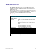

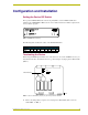
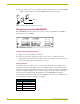
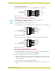
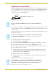
Table Of Contents
Configuration and Installation
4
AXB-DMX512 DMX512 Interface
2. Place the jumper on pins 2 and 3 of jumper trios JP4 and JP5. (Pins 2 and 3 are marked TERM
-see FIG. 3). This terminates the incoming DMX input with a 120 ohm resistor.
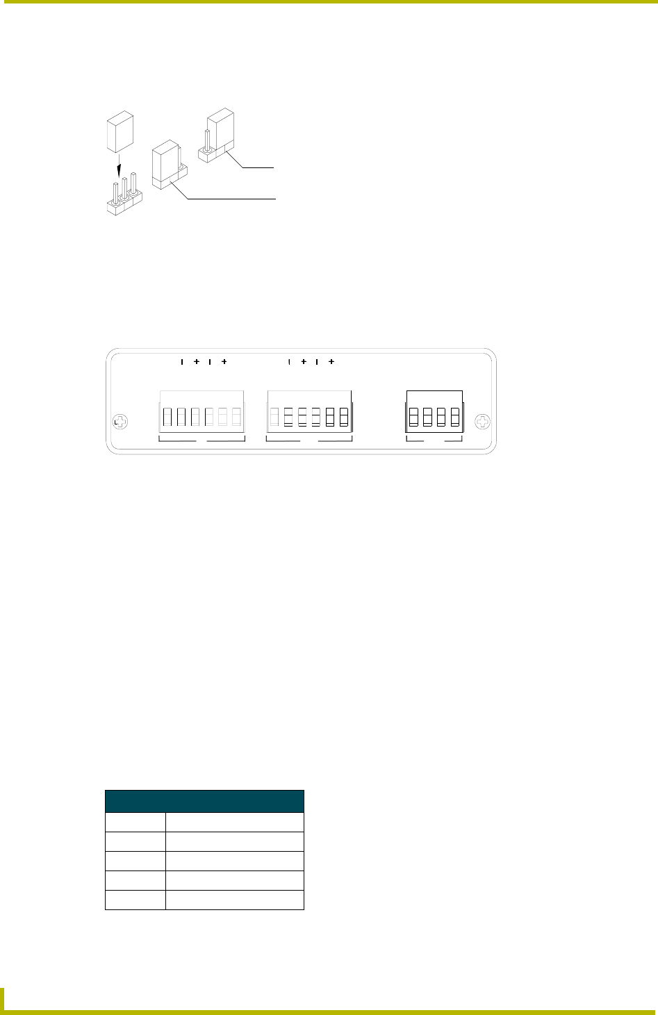
Wiring Devices to the AXB-DMX512
The AXB-DMX512 has three captive-wire connectors on the rear panel (FIG. 4) for DMX512
transmit and receive, and AXlink.
Preparing/connecting captive wires
1. Strip 0.25 inch of wire insulation off all wires.
2. Insert each wire into the appropriate opening on the connector according to the wiring
diagrams and connector types described in this section. Do not tighten the screws excessively;
doing so may strip the threads and damage the connector.
Wiring guidelines
The interface requires a 12 VDC power to operate properly. The interface uses a PSN2.8 power
supply. The Central Controller supplies power via the AXlink cable or external 12 VDC power
supply. The maximum wiring distance between the Central Controller and interface is determined
by power consumption, supplied voltage, and the wire gauge used for the cable. The table below
lists wire sizes and maximum lengths allowable between the AXB-DMX512 and Central
Controller. The maximum wiring lengths for using AXlink power are based on a minimum of 13.5
volts available at the Central Controller’s power supply.
FIG. 3 Termination jumper pin settings for JP4 and JP5
FIG. 4 AXB-DMX512 (rear view)
Wiring Guidelines at 160 mA
Wire Size Maximum Wiring Length
18 AWG 733.57 feet (223.59 m)
20 AWG 464.11 feet (141.46 m)
22 AWG 289.35 feet (88.19 m)
24 AWG 182.39 feet (55.59 m)
TERM
HIZ
IN OUT AXlink
DATA
GND
GND
DATA
DATA
DATA
NC
DATA
DATA
DATA
DATA
NC
GND
AXP
AXM
PWR
1
2
1
2
1
1
2
2