
User Guide

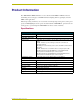

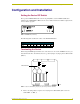
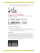
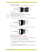
Table Of Contents
Configuration and Installation
3
A
XB-DMX512 DMX512 Interface
Configuration and Installation
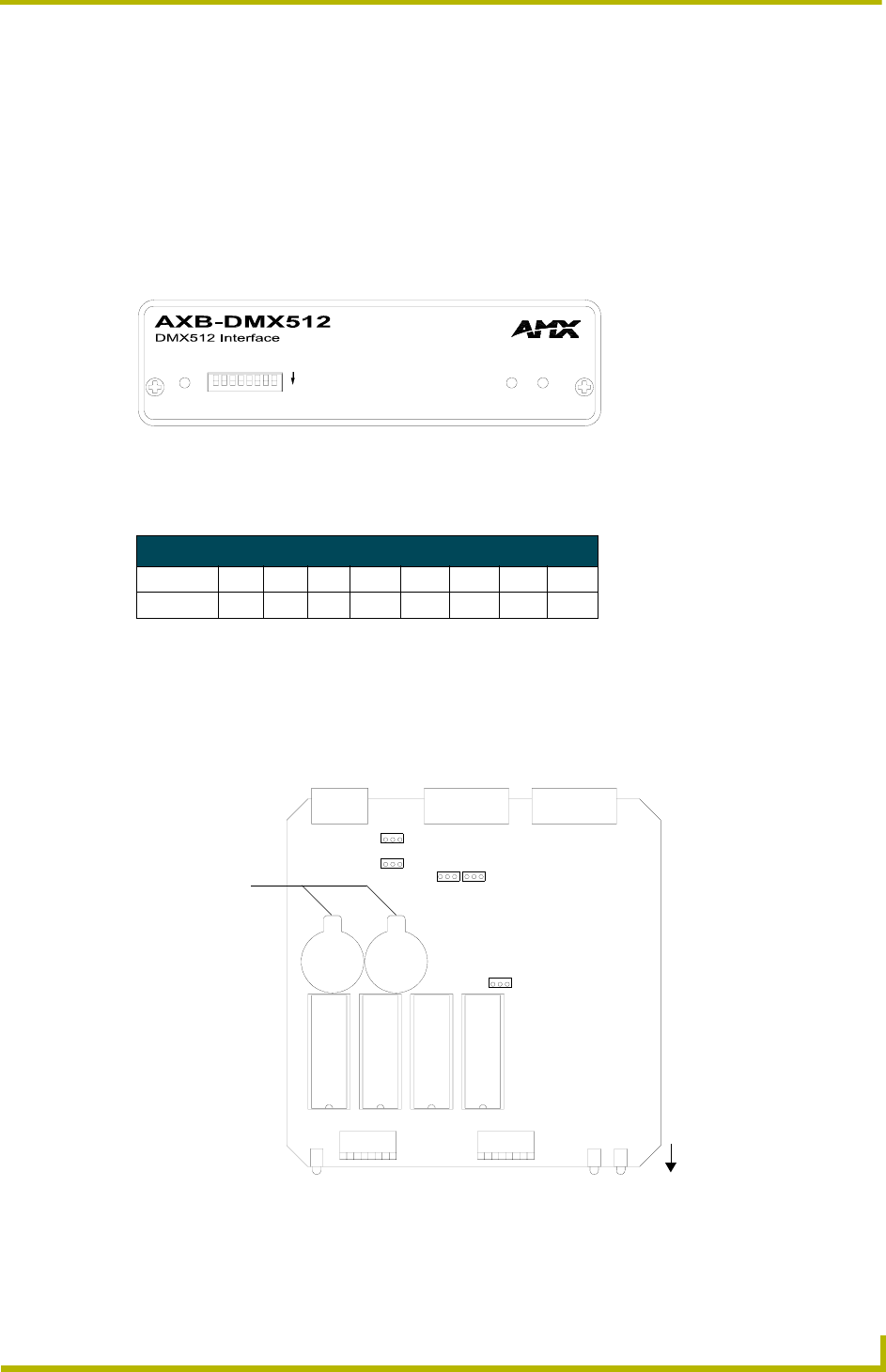
Setting the Device DIP Switch
The 8-position DEVICE DIP switch on the front panel (FIG. 1) sets the AXlink identification
number for the AXB-DMX512. Make sure the device number matches the number assigned in the
Axcess software program.
The following table describes the values on the
DEVICE DIP switch.
Terminating the Device
When using the DMX input and if this device is the last device in a chain of DMX512 devices, you
must terminate the line. To terminate the device, position jumpers on jumper pin trios JP4 and JP5
(FIG. 2):
1. Remove the jumper that is on pins 1 and 2 of jumper trios JP4 and JP5. (Pins 1 and 2 are
marked HIZ - see FIG. 3).
FIG. 1 AXB-DMX512 (front view)
Device DIP Switch Settings
Position 12345678
Value 1 2 4 8 16 32 64 128
FIG. 2 Location of termination jumpers pins (JP1-JP5) and lithium batteries
AXlink
DEVICE
ON
RXTX
COR
Lithium Batteries
JP2
JP3
JP5
JP4
JP1
front