instruction manual AXB-DMX512 DMX512 Interface AXlink Bus Controllers
AMX Limited Warranty and Disclaimer AMX Corporation warrants its products to be free of defects in material and workmanship under normal use for three (3) years from the date of purchase from AMX Corporation, with the following exceptions: • Electroluminescent and LCD Control Panels are warranted for three (3) years, except for the display and touch overlay components that are warranted for a period of one (1) year.
Table of Contents Table of Contents Product Information .................................................................................................1 Specifications .................................................................................................................... 1 Configuration and Installation .................................................................................3 Setting the Device DIP Switch..............................................................................
Table of Contents ii AXB-DMX512 DMX512 Interface
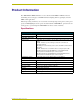
Product Information Product Information The AXB-DMX512 DMX512 Interface creates a bi-directional DMX512 AXlink connection, transmitting and receiving up to 512 DMX channels for lighting dimmers, spotlights, and other DMX control applications. Onboard processing and memory can create and store channel groups, faders, patches, and up to 72 presets.
Product Information 2 AXB-DMX512 DMX512 Interface
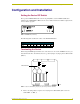
Configuration and Installation Configuration and Installation Setting the Device DIP Switch The 8-position DEVICE DIP switch on the front panel (FIG. 1) sets the AXlink identification number for the AXB-DMX512. Make sure the device number matches the number assigned in the Axcess software program. AXlink DEVICE TX RX ON FIG. 1 AXB-DMX512 (front view) The following table describes the values on the DEVICE DIP switch.
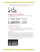
Configuration and Installation 2. Place the jumper on pins 2 and 3 of jumper trios JP4 and JP5. (Pins 2 and 3 are marked TERM -see FIG. 3). This terminates the incoming DMX input with a 120 ohm resistor. TERM HIZ FIG. 3 Termination jumper pin settings for JP4 and JP5 Wiring Devices to the AXB-DMX512 IN OUT AXP PWR AXM GND DATA 2 NC DATA 2 DATA 1 GND DATA 1 DATA 2 NC DATA 2 DATA 1 GND DATA 1 The AXB-DMX512 has three captive-wire connectors on the rear panel (FIG.
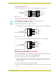
Configuration and Installation Using AXlink communication Connect the AXlink wiring to the connector on the AXB-DMX512, as shown in FIG. 5. AXlink connector on AXB-DMX512 PWR PWR AXP AXP AXM AXM GND GND Device FIG. 5 AXlink wiring Using IN and OUT DMX512 data communication Some DMX devices only use DATA+ and DATA-. Connect these to DATA1+ and DATA1-, leaving DATA2+ and DATA- unconnected. The DATA2 In and Out ports are not Currently supported. 1.
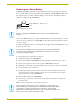
Configuration and Installation Replacing the Lithium Battery A lithium battery (FIG. 8) with a life of approximately 5 years, protects stored presets if a power loss occurs. The battery is not used when DC power is supplied to the AXB-DMX512. Write down the replacement date on a sticker or label by adding 5 years to the date of installation, and then attach it to the bottom of the AXB-DMX512. Battery (CR2032 type - 20mm coin cell) socket FIG.
Configuration and Installation AXB-DMX512 DMX512 Interface 7
Configuration and Installation 8 AXB-DMX512 DMX512 Interface
Programming Programming The AXB-DMX512 is controlled with Axcess Send_Commands. Use the programming information in this section along with the Axcess Programming Language Instruction Manual to program the AXB-DMX512. All Send Commands are limited to 64 characters. Buffers The AXB-DMX512 uses a “highest value takes precedence” to determine which DMX value is actually output (see FIG. 9). There are three output buffers: patch, group, and direct control. Each buffer represents all 512 DMX outputs.
Programming Direct Control Buffer Send_Commands The direct control buffer is modified by individual output ramps or by preset recalls. The following table lists the Direct Control Buffer Send_Commands. Direct Control Buffer Send_Commands Command Description DL Time is required here. This affects all DMX512 channels. Recalls a snapshot of all DMX output channel in T tenths of seconds. Syntax: "'DLT
Programming Direct Control Buffer Send_Commands Command Description DS This is the final output of the DMX512 box and is also affected by the values in the Patch and Group Buffers. Stores a snapshot of all DMX output channels. Note that this command stores all DMX512 channels, even channels that are not currently being transmitted through the use of the ‘ML’ command (refer to the Miscellaneous Send_Commands section on page 23).
Programming Patch Buffer Send_Commands (Cont.) Command Description PC The list can be single outputs and/or ranges of outputs separated by commas. If the output is currently already patched to another input, then it is automatically disconnected from that input. Patches an input to one or more outputs. Syntax: "'PCD'" Variables: DMX Input = 1-512.
Programming Group Buffer Commands The group buffer is modified by changing group commands. There is a maximum of 96 groups in software version 1.10. Adding outputs to a group while the group is still connected to an Axcess level DMX output can cause the value of outputs, which are already a member of the group, to change. The following table lists the Group Buffer Send_Commands. Group Buffer Commands Command Description GA The list can be single outputs and/or ranges of outputs separated by commas.
Programming Group Buffer Commands (Cont.) Command Description GC A group can only be tied to one or the other not both. The list can be single groups and/or ranges of groups separated by commas. Connects one or more groups to an Axcess level or to a DMX input. Syntax: "'GC'" Variables: Axcess level = 1-8 DMX input = 1-512 If a single group is connected to an unconnected Axcess level, then the Axcess level value will change to the group value.
Programming Group Buffer Commands (Cont.) Command Description GD The group stop (‘GS’), group ramp down (‘GD’), or group direct ramp command (‘GR’) will interrupt this command. It is not possible to use this command on groups that are connected to an Axcess level or to a DMX input. Ramps down one or more groups at the current ramp rate set by the ‘GT’ command. Syntax: "'GD'" The list can be single groups and/or ranges of groups separated by commas.
Programming Group Buffer Commands (Cont.) Command Description GL This command removes one or more output channels from the group that they are connected to. These outputs go immediately to 0% in the Group buffer. Deletes DMX outputs from any group. DO NOT specify which group these are to be removed from, because a channel can only be a member of one group at a time. The list can be single outputs and/or ranges of outputs separated by commas.
Programming Group Buffer Commands (Cont.) Command Description GP The highest the DMX output can ever be is the value at the time of the add. A DMX output can only belong to one group at a time. Same as ‘GA’ command, except the DMX outputs are added so they will remain proportional to the value they had at the time of adding the output. The outputs will not ramp to a value above that which they had at the time they were added.
Programming Group Buffer Commands (Cont.) Command Description GR Ramps a single group to a level. Time is optional and if no time is specified, the group time (set by the ‘GT’ command) is used and then it will ramp at the current ramp rate for that group. If a group is tied to a DMX input, then this command is ignored. If the group is tied to an Axcess level the group will ramp. Ramps group to a L level in T tenths of seconds.
Programming Group Buffer Commands (Cont.) Command Description GT This affects any future group up (‘GU’), group down (‘GD’), or group direct ramp (‘GR’) commands. The specified time determines how long it takes to go full range. If the group is proportional then Individual Output rates will be proportional. Sets the current ramp rate for one or more groups in tenths of a second. Optionally, the up (‘U’) or down (‘D’) times may be specified.
Programming Group Buffer Commands (Cont.) Command Description GX This command disconnects one or more groups from Axcess levels or DMX inputs that they are connected to. Disconnects groups from Axcess level or DMX level. The list can be single groups and/or ranges of groups separated by commas. Syntax: "'GX'" Example: SEND_COMMAND DMX,'GX1' Disconnects Group 1. SEND_COMMAND DMX,'GX5,10-15' Disconnects Groups 5 and 10 through 15. GZ Disconnects and erases all groups.
Programming Axcess Level Send_Commands (Cont.) Command Description AD Ramps until ‘AS’, ‘AR’, or ‘AU’. Note that it is not possible to ramp an Axcess level if it has not been connected to a DMX input (using the ’AC’ command). Ramps down one Axcess level at the ramp rate set by the ‘AT’ command. Syntax: "'AD'" Variable: Axcess level = 1 - 8 Example: SEND_COMMAND DMX,'AD1' Ramps down Axcess level 1. AR Ramps a single Axcess level to the chosen L level in T tenths of seconds.
Programming Axcess Level Send_Commands (Cont.) Command Description AT This affects any future level up (‘AU’), level down (‘AD’), or level direct Sets the ramp rate for one Axcess level ramp (‘AR’) commands. The specified time determines how long it takes to go full range. If the group is proportional then Individual in tenths of a second. Output rates will be proportional. Optionally, the up (‘U’) or down (‘D’) times may be specified.
Programming Miscellaneous Send_Commands The following table lists other miscellaneous Send_Commands. Miscellaneous Send_Commands Command Description MB The range is from 88 to 10,000 microseconds. Sets the break time. Syntax: "'MB
Programming Miscellaneous Send_Commands (Cont.) Command Description ML Default and maximum is 512. The number of packets sent per second Defines the number of output that are will increase accordingly, this can cause the break-to-break time to transmitted. Limits the number of chan- drop below the official minimum time of 1,196 microseconds. This takes place downstream from the AXB-DMX512s’ output buffer and nels in the transmitted DMX packet. has no affect on any other commands.
Programming Miscellaneous Send_Commands (Cont.) Command Description MR Type is optional. This macro command sets ‘MB’, ‘MD’, ‘ML, and ‘MM’ to send either 44 or 22 packets per second with 512 channels of DMX outputs. Syntax: "'MR{ }'" Variable: No Type or Type = 0: 44 packets per second. Type = 1 is 22 packets per second. {}-Parameters in commands that are optional. Example: SEND_COMMAND DMX,'MR0' Sets the parameters for 44 packets per second at 512 packets per packet.
Programming Channel Trigger Send_Commands Almost all methods of control using an Axcess system require the use of channels on devices. The following table lists the channel trigger Send_Commands. Channel Trigger Send_Commands Command Description CA The minimum value must be specified, but the maximum value is optional. If not specified, the maximum value is assumed to be 100% (255). When the DMX input is equal to low, then the Axcess channel will turn on.
Troubleshooting Troubleshooting Thi section addresses and provides solutions to most frequently asked questions. AXB-DMX512 Troubleshooting Problem Solution: The transmit LED on the DMX512 is always On. Is this a failure? • Unlike most serial protocols, the DMX512 transmits a constant stream of data. This means that since the DMX512 is constantly receiving data, its receive LED should always be On during that process.
brussels • dallas • los angeles • mexico city • philadelphia • shanghai • singapore • tampa • toronto* • york 3000 research drive, richardson, TX 75082 USA • 469.624.8000 • 800.222.0193 • fax 469.624.7153 • technical support 800.932.6993 032-004-1412 11/04 ©2004 AMX Corporation. All rights reserved. AMX, the AMX logo, the building icon, the home icon, and the light bulb icon are all trademarks of AMX Corporation. AMX reserves the right to alter specifications without notice at any time.