Operation/Reference Guide AVS-SL-PR-0201-0301 Solecis Presentation Switcher 2x1:2 RGBHV, 3x1 SVID, 5x1 Stereo, CP S ol e c i s S w it che r s Initial Release:: 6/30/2008
AMX Limited Warranty and Disclaimer This Limited Warranty and Disclaimer extends only to products purchased directly from AMX or an AMX Authorized Partner which include AMX Dealers, Distributors, VIP’s or other AMX authorized entity.
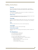
Safety Instructions Safety Instructions Overview Please read these instructions before using your Solecis switcher. Failure to comply with these instructions could result in fire, electrical shock, personal injury, death, or damage to the equipment. Power Source Use only a three-wire grounding type source. The power source should not exceed 264VAC. Do not remove under any circumstances the ground wire. Power Cord Use only the cord shipped with the unit.
Safety Instructions Solecis AVS-SL-PR-0201-0301 Presentation Switcher
Table of Contents Table of Contents Safety Instructions .............................................................................................. a Overview .................................................................................................................. a Power Source............................................................................................................ a Power Cord...................................................................................................
Table of Contents Serial Commands ..............................................................................................13 Communication Protocol......................................................................................... 13 Command Set ........................................................................................................ 13 Decoding the Front Panel Status ........................................................................... 14 Troubleshooting .................
Overview Overview The Solecis AVS-SL-PR-0201-0301 Presentation Switcher (FG1330-2020-01) combines switching of PC, computer, video and audio for presentation and conference rooms, home cinema, AV Rental Companies and any environment where a number of mixed source types need to be displayed. (front) (rear) FIG. 1 Solecis AVS-SL-PR-0201-0301 Presentation Switcher The AVS-SL-PR-0201-0301 features a total of 5 AV inputs and a programmable serial output for controlling projectors, plasma and LCD displays.
Overview Product Specifications AVS-SL-PR-0201-0301 Specifications RGB RGB Inputs: 2 Connector: HD-15 Level: Analog Max Level: 1V p-p Impedance: 75 ohm Bandwidth 250MHz -3dB Return Loss -38dB @ 10MHz, -20dB @ 100MHz Adjacent Input Crosstalk: -80dB @ 10MHz, -70dB @ 100MHz Sync Input Level: TTL / Analog Max Level: 5V p-p Impedance: 75 ohm Video Input Number: 3 Connectors: RCA & 4 pin mini din S-Video Type: CV or YC Bandwidth: 50 MHz -3dB Differential Phase Error: 0.
Overview AVS-SL-PR-0201-0301 Specifications (Cont.) Video Output Number 2 Connectors RCA & 4 pin mini din S-Video Audio Output Connector RCA & Captive-wire Switched 1 unbalanced with volume control Mixed 1 balanced / unbalanced Impedance 600 ohm Power: • 110-240V 50/60Hz Power Consumption: 15W Dimensions (HWD): 44 x 441 x 174 Weight: 1.
Overview 4 Solecis AVS-SL-PR-0201-0301 Presentation Switcher
Connections Connections Make sure the unit is unplugged from the mains power source while making initial connections. PC Connections 1. Connect the PC sources to the sockets labelled PC 1 & PC 2. 2. Connect the primary output to Output 1 and then if a secondary output is required, connect it to Output2. 3. Connect the audio sources for the PC inputs to the inputs labelled PC 1 & PC 2 in the audio block. Video Connections 1.
Connections Serial Control Connections Connect the display device serial control to the screw terminals labelled Display Tx & Rx. For setting up the equipment and for remote control of the switch connect to the PC Comms Tx & Rx terminals. The ground terminal is shared between the two connections. Don't forget to cross connect the serial devices so the TX goes to RX and RX goes to TX and GROUND goes to GROUND. Please double check all connections before connecting power to the unit.
Configuration Configuration Overview In order to correctly set up the AVS-SL-PR-0201-0301 switch please download the Solecis Device Manager software from our website - www.Solecis.co.uk then click on support. Once installed, make sure the switch is connected correctly to a PC serial port and then start the device installer software. The software will scan the serial ports on the PC and find the attached device (FIG. 2). FIG.
Configuration Microphone Setup Clicking the set up microphone button brings up the window shown in FIG. 4. Dragging the arrows allows increase and decrease of a setting whilst centre all sets the values back to their middle value. FIG. 4 Microphone setup To return to the main screen click on back. Display Setup Click on the set up display device button brings up the window shown in FIG. 5. From here you can tell the switcher what device is attached by selecting the make, type and model from the list.
Configuration Sources Setup Clicking on set up sources brings up FIG. 6. This allows you to set the volume attenuation levels for each of the audio inputs. When the master volume on the front panel is adjusted, it adjusts all of the input volume controls up to the point where the first input hits the maximum or minimum.
Configuration 10 Solecis AVS-SL-PR-0201-0301 Presentation Switcher
Operation Operation Power On This button turns the display device on, the button lights to show the current status. Power Off This button turns the display device off, the butt on lights to show the current status. PC1 & PC2 These button allow input selection of the two PC inputs. The button lights to reflect the press. Video 1, 2 & 3 Same as PC1 & PC2 but for the video inputs. AUX Same again but for the auxiliary audio input. This can only be selected in AV & Audio modes.
Operation 12 Solecis AVS-SL-PR-0201-0301 Presentation Switcher
Serial Commands Serial Commands Communication Protocol Baud - 9600 Data Bits - 8 Stop Bits - 1 Parity - None Command Set Serial Commands Command Description Acknowledge Returned F2 09 EA 80 Requests Solecis device code – Header 6E, 2020 = 1D 6E 1D 9F 15 05 Simulates display device power on button 9F 15 05 9F 15 06 Simulates display device power off button 9F 15 06 9F 15 07 Simulates PC1 input button 9F 15 07 9F 15 08 Simulates PC2 input button 9F 15 08 9F 15 09 Simulates Video 1 input b
Serial Commands Serial Commands (Cont.) 9F 15 21 Audio Mode 9F 15 21 9F 15 22 Video Mode 9F 15 22 9F 15 40 PC Blank On 9F 15 40 9F 15 41 PC Blank Off 9F 15 41 9F 15 44 Video Blank On 9F 15 44 9F 15 45 Video Blank Off 9F 15 45 9F 15 48 Audio Mute On 9F 15 48 9F 15 49 Audio Mute Off 9F 15 49 These commands are global, if you have a unit address set these commands will override the address and still switch the unit.
Troubleshooting Troubleshooting Q. Device Installer can't find my switch. Make sure that the serial connections are wired correctly, tx to rx, rx to tx and ground to ground. If using a USB adapter, try removing it and plugging it in to a different USB port on the PC. Make sure the PC is connected to the PC communications port and not the display's communication port. Q. My display device does not respond to button presses. Make sure the system is configured for the correct display device.
Troubleshooting 16 Solecis AVS-SL-PR-0201-0301 Presentation Switcher
Troubleshooting Solecis AVS-SL-PR-0201-0301 Presentation Switcher 17
AMX. All rights reserved. AMX and the AMX logo are registered trademarks of AMX. AMX reserves the right to alter specifications without notice at any time. ©2008 6/08 It’s Your World - Take Control™ 3000 RESEARCH DRIVE, RICHARDSON, TX 75082 USA • 800.222.0193 • 469.624.8000 • 469-624-7153 fax • 800.932.6993 technical support • www.amx.