
Instruction manual


Control Panel Operation
61
Epica DGX 16 and Epica DGX 32 Instruction Manual
Executing Switches
A switch is an active connection between an input (source) device and one or more output (destination)
devices. The signals routed in a switching operation are individual signals or groups of individual signals
coming through the connectors on the rear of an enclosure. You can execute switches from the Control
Panel using the steps below or by defining and executing a global preset (see page 65) or by executing a
local preset (see page 67).
The LCD displays VM 0 or VM 1 (or any custom virtual matrix) in the upper-right corner; this is the
virtual matrix that operations are currently being executed on. Switches are executed on the default
virtual matrix unless otherwise specified. When specifying a virtual matrix, be sure it includes the
signal(s) you want to route.
Note: When audio is transmitted along with the video over the fiber, the audio switches on the same
VM as the video (the audio and video cannot be switched independently).
Note: When using the control panel on an Epica DGX 16 or 32 to control a larger matrix switcher
in a linked system, the number of inputs and outputs that can be controlled on the larger matrix
switcher cannot be greater than the number of ones available on the Epica DGX 16 or 32. The
virtual matrices on the larger matrix switcher must be configured accordingly.
Virtual matrix definitions reside in the configuration information in an enclosure’s CPU. If you need to
change the virtual matrix, see “Changing the Virtual Matrix” on page 62. If you decide to change the
default virtual matrix, see page 73 for “Setup Options.”
When an Input or Output Key is pressed, the LCD displays the channel name (e.g., O_Ch:0003 for
Output 3). Hold the key down to display the name longer.
You can return to the Function menu at any time by pressing the Function Key.
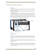
Note: When you put the panel in Change Mode, available keys will be blue and any unavailable
ones will not be illuminated. The first blue key selected flashes white and the next key(s) selected
turns white. You can toggle the non-flashing white keys between the selected (white) and unselected
(blue) state before pressing the Take Key. For an example, see FIG. 37 on page 58.
In an execute switch command either an input or an output may be selected first. To switch to multiple
outputs, the Input Key must be selected first. With the Control Panel you can select and unselect Input
and Output Keys to modify the switch as long as the keys are not flashing. Once satisfied with the switch
selections, press the Take Key to execute it. (Or, if not satisfied with the selections, press the Cancel Key
and start over.)
For new installations, we recommend executing a test switch to verify the system is working correctly
before attaching all inputs and outputs. To execute a test switch, attach the first input (source) and first
output (destination) and then complete the directions below. For more information on test switches, see
page 40.
The directions below switch Input 1 to Output 1 on the currently selected virtual matrix.
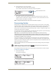
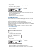
To execute a test switch:
1.
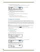
Press the Function Key.
The Function menu appears.