
Instruction manual

Installation and Setup
30
DGX Transmitters & Receivers Instruction Manual
To attach signal cables to a TX:
1.
Check the EDID switch on the rear of the TX to be sure that it remains in the down position for
WP (write protect).
2. DGX HD-15 TX – Attach the connector on the HD-15 cable from the source device to the Video Input
receptacle (FIG. 20, top). HD-15 connectors on the module use the pinout information in FIG. 17.
or
DGX DVI TX
– Attach the connector on the DVI cable from the source device to the Video Input
receptacle (FIG. 20, bottom). DVI connectors on the module use the pinout information in FIG. 18.
3. Optional – To use the local out option for a nearby video destination device, attach the device’s cable to
the Local Video Output receptacle.
4. If needed – Insert the connector on the digital or analog stereo audio cable from the source device into
the appropriate input audio jack, Digital or Stereo. Digital takes precedence if both are connected.
CAUTION – CLASS 3R INVISIBLE LASER RADITION WHEN OPEN; AVOID DIRECT EYE EXPOSURE.
5. Clean the fiber cable connector. Follow the manufacturer’s recommendations.
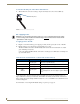
6. Remove the dust plug from the SC Fiber Output jack* and insert the fiber cable connector (the fiber
connector will click when fully engaged).
7. Connect the open end of the SC fiber cable to the RX before connecting power.
* The fiber jack is a standard 2.5 mm SC fiber connector (standardized in TIA-568A) that snaps the cable
connector into place.
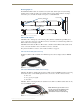
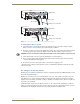
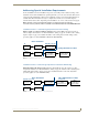
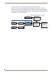
FIG. 20 Attach signal cables to DGX HD-15 TX (top) or DGX DVI TX (bottom)
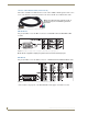
SC fiber cable
DVI cable
SC fiber cable
Analog stereo audio cable
HD-15 cable
EDID switch must be set to WP
EDID switch must be set to WP
Analog stereo audio cable
Digital audio
Digital audio