
Instruction manual

Overview and Specifications
15
DGX Transmitters & Receivers Instruction Manual
AVB-RX-DGX-SC Fiber-DVI
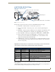
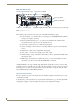
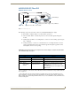
DGX DVI RX Front View
The following components are located on the front of the DGX DVI RX (left to right):
Power LED – indicates whether or not the module is powered on.
Video and Audio LEDs – indicate the presence of video and audio signals through the
module.
Scaling button and LEDs – use Scaling button to select one of the 3 Scaling options: Bypass,
Auto, or Manual.
USB port (mini-B) – connect to a control PC and use for overriding automatic conversion
settings, signal adjustment, if necessary, firmware upgrades through an Upgrade Tool, live
status updates, and error code reporting.
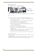
Important: If the indicator LEDs do not respond with a normal display as stated in the table below,
see “Troubleshooting” on page 57.
* When a USB cable is connected, the Power LED blinks red while communication is being established with the
PC (see page 67).
** If the output cable is disconnected from the RX or if no EDID can be found on the destination device, the
Bypass LED will be constant green and the Auto LED will blink. This indicates that the RX has switched to the
Bypass Scaling option and is waiting for EDID information. As soon as a valid EDID is found, the RX will revert to
the Auto Scaling option.
FIG. 7
DGX DVI RX front view
RX Indicator LEDs
LED Normal Display Indicates
Power* Constant green Power is applied to module.
Video Constant green A video signal is present through module.
Audio Constant green An audio signal is present through module.
Scaling –
Bypass
–
Auto (default)
–
Manual
One is constant green;
the other two are off
Module is in one of the three modes for scaling.
At initial power up, the RX defaults to the Auto
Scaling option.**
Press Scaling button to turn on the Bypass option
or Manual option.
Signal presence LEDs - Video & Audio
Power LED
Scaling button & LEDs - Bypass, Auto, & Manual
USB mini-B port