
Instruction manual

Overview and Specifications
11
DGX Transmitters & Receivers Instruction Manual
AVB-TX-DGX-DVI-SC Fiber
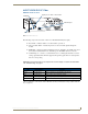
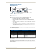
DGX DVI TX Front View
The following components are located on the front of the DGX DVI TX (left to right):
Power LED – indicates whether or not the module is powered on.
Video and Audio LEDs – indicate the presence of video and audio signals through the
module.
EDID LED – when the module is in Write-Protect mode, the LED is off (default state); when
the module is in Write-Enable mode, the LED is green. The EDID switch is on the rear.
USB mini-B port – connect to a control PC and use for overriding the automatic conversion
settings, signal adjustment, firmware upgrades through an Upgrade Tool, live status updates,
and error code reporting.
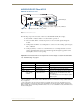
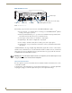
Important: If the indicator LEDs do not respond with a normal display as stated in the table below,
see “Troubleshooting” on page 57.
* When a USB cable is connected, the Power LED blinks red while communication is being established with the
PC (see page 67).
FIG. 3
DGX DVI TX front view
TX Indicator LEDs
LED Normal Display Indicates
Power* Constant green Power is applied to module (initially red at start up).
Video Constant green A video signal is present through module.
Audio Constant green An audio signal is present through module.
EDID Off EDID is in Write-Protect mode (EDID switch on rear flipped down).
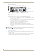
EDID LED
Power LED
Signal presence LEDs - Video & Audio
USB mini-B port