instruction manual AV2SM A/V Switcher C on t ro l S y s t em A c c e s s or ie s
AMX Limited Warranty and Disclaimer AMX Corporation warrants its products to be free of defects in material and workmanship under normal use for three (3) years from the date of purchase from AMX Corporation, with the following exceptions: • Electroluminescent and LCD Control Panels are warranted for three (3) years, except for the display and touch overlay components that are warranted for a period of one (1) year.
Table of Contents Table of Contents Product Information .................................................................................................1 Specifications .................................................................................................................... 1 Installation .................................................................................................................3 Automatic and Manual Switching Mode Settings ................................................
Table of Contents ii AV2SM A/V Switcher
Product Information Product Information The AV2SM A/V Switcher is a media interface device you can set to automatically or manually switch between two A/V input sources, outputting to a display monitor connected to the front panel.
Product Information Specifications (Cont.) Rear Panel: INPUT A VIDEO BNC female connector INPUT A AUDIO 6-pin cable jack, audio and control input INPUT B VIDEO BNC female connector INPUT B AUDIO 4-pin cable jack Captive-wire screw terminals Allows stereo (unbalanced) line-level audio Switching Modes: Automatic AV2SM switches to the A source; if no input is detected the AV2SM automatically switches to the B source. If both A and B sources are present, the default is the A source.
Installation Installation You can install the AV2SM on any flat surface that has unobstructed access to both the front and rear panel connectors. Automatic and Manual Switching Mode Settings You can select the switching mode by setting two internal jumpers on the circuit card inside the enclosure. You will need a Phillips screwdriver to open the enclosure. To set the switching mode: 1. Discharge the static electricity from your body and screwdriver. 2.
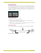
Installation Wiring Guidelines The maximum wiring distance between the Central Controller and the AV2SM is determined by power consumption, supplied voltage, and the wire gauge used for the cable. The maximum wiring lengths for using AXlink power are based on a minimum of 13.5 volts available at the Central Controller’s power supply. The maximum lengths allowable between the AV2SM and the Central Controller are as follows: Wiring Guidelines Wiring size Maximum wiring length 18 1805.7 ft (550.
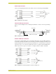
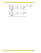
Installation Audio output connector Connect your output display monitor to the Audio connector on the front panel using FIG. 5. LEFT LEFT GND GND GND GND RIGHT Audio source output RIGHT AV2SM AUDIO INPUT connector FIG. 5 AUDIO OUTPUT wiring diagram Video A and B input connectors Connect your Video Output source to the Input A and B Video connector on the rear panel using FIG. 6.
Installation SELECT LEFT GND GND RIGHT GND SELECT LEFT GND GND RIGHT Output (audio source) GND External relay closure AV2SM AUDIO INPUT A LEFT GND GND RIGHT LEFT GND GND RIGHT Output (audio source) AV2SM AUDIO INPUT B FIG.
Installation AV2SM A/V Switcher 7
brussels • dallas • los angeles • mexico city • philadelphia • shanghai • singapore • tampa • toronto • york 3000 research drive, richardson, TX 75082 USA • 469.624.8000 • 800.222.0193 • fax 469.624.7153 • technical support 800.932.6993 041-004-1101 9/01 ©2001 AMX Corporation. All rights reserved. AMX, the AMX logo, the building icon, the home icon, and the light bulb icon are all trademarks of AMX Corporation. AMX reserves the right to alter specifications without notice at any time.