
Instruction manual


Installation and Setup
16
Instruction Manual – Precis DSP Matrix Switchers
Attaching Inputs and Outputs
Input and output connectors are the attachment points for source and destination devices that connect to the system.
Viewed from the rear of a Precis DSP enclosure, the inputs (for sources) are on the left side of the enclosure, and the
outputs (for destinations) are on the right side.
Precis DSP models have gold-plated RCA connectors for routing stereo audio. Each input and output consists of a pair of
connectors (left and right) with the number of the input/output between the two connectors.
Before connecting all input and output cables, attach only the first two input and output pairs and execute a test switch
(see page 19).
When the test switch is successful, attach the rest of the input and output cables.
To attach RCA cables:
1.
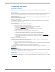
Insert the RCA plugs into the input and output RCA jacks according to the labels on the enclosure (FIG. 4).
The system is ready to apply power; see below.
Applying Power
The enclosure’s universal power receptacle will accept all major international standard power sources.
A standard US power cord is provided for installations within the US. Maximum power specifications are on the power
receptacle (also listed on page 11). Always use an earth-grounded power cord / system with a Precis DSP.
The source electrical outlet should be installed near the Precis DSP, easily accessible, and properly grounded. Power
should come from a building branch circuit. We strongly recommend using a dedicated line for the system’s power. Use
a minimum breaker current rating of 15 A for 110 V or 30 A for 230 V.
To avoid an overload, note the power consumption rating of all the equipment connected to the circuit breaker before
applying power.
Power-Up Sequence
To apply power:
1.
Attach the first two source and destination devices; see page 16.
Do not apply power to the source and destination devices until Step 5.
2. Plug the power cord into the power receptacle on the enclosure.
3. Plug the other end of the power cord(s) into a power strip that is turned off (we recommend using a 30 A power
strip).
4. Turn on the power strip.
5. Press the “I” side of the enclosure’s power switch.The Power Indicator on the front of the enclosure illuminates.
6. Apply power to the source and destination devices.
The system is ready to attach a serial controller. A PC is required to run the APGraphic EQ software for system setup;
see page 17.
FIG. 4 Insert RCA plugs into RCA jacks
Caution: We recommend attaching all power cords to a surge protector and/or an AC line conditioner.