
Instruction manual


Installation and Setup
15
Instruction Manual – Precis DSP Matrix Switchers
Installation Procedure
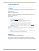
A flow chart showing the basic installation sequence is in FIG. 2. The procedure which follows provides general steps
with references to detailed information found in later sections of this chapter. After the basic sequence is complete, see
page 21 for fine tuning the audio with APGraphic EQ.
To install and set up a Precis DSP in a rack:
1.
On the side of the Precis DSP, remove the bottom two screws closest to the front panel (FIG. 3). Align the holes on
one of the rack ears with the empty holes on the side of the enclosure and replace the screws (three screws for the
1 RU; four screws for the 2 RU).
Repeat for the other rack ear.
2. Place the enclosure in the rack and attach front-mounting screws to hold it firmly in place.
3. Attach only the first two source devices and the first two destination devices; see page 16.
Do not apply power to the devices until after the Precis DSP has power (Step 4).
4. Apply power to the system according to the power-up procedure; see page 16.
Note: We recommend using a surge protector and/or an AC line conditioner.
5. Connect the Precis DSP to the PC and establish communication; see page 17.
6. Install and open the APGraphic EQ software on the PC; see page 18.
7. Execute a test switch to ensure the system is working properly; see page 19.
8. When the test switch works correctly, attach the remaining source and destination devices.
9. Fine tune the system for optimum performance using APGraphic EQ; see the “Fine-Tuning with APGraphic EQ”
chapter on page 21.
10. Establish communication with the desired external control device/system; for control options, see page 17.
FIG. 2 Installation procedure
Caution: To prevent overheating and airflow restriction, avoid placing high-heat producing equipment
directly above or below the enclosure. The system requires a minimum of one empty rack unit above and
below. Verify that the openings on the sides of the enclosure are not blocked and do not have restricted air
flow.
FIG. 3 Attach rack ears to sides of enclosure
Remove and then replace
Insert
Front Panel
Insert
Remove and then replace
2 RU
1 RU
Front Panel