FRONT COVER
Manual - Inside Front Cover (Blank)
Table of Contents Important Information . . . . . . . . . . . . . . . . . . . . . . . . . . . 2 Recommended Installation Tools . . . . . . . . . . . . . . . . . . . . 2 Recommended Procecures . . . . . . . . . . . . . . . . . . . . . . . 2 Wiring Diagram . . . . . . . . . . . . . . . . . . . . . . . . . . . . . . 3 14 Pin Connector . . . . . . . . . . . . . . . . . . . . . . . . . . . . 4 Installation Procedures. . . . . . . . . . . . . . . . . . . . . . . . . . . 5 Control Unit. . . . . . . . . . . . . . .
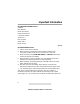
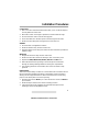
Important Information Recommended Installation Tools Voltmeter Wire Strippers Electric Drill & Bits Phillips Screw Driver Convoluted Tubing * Solder Gun * Wire Crimpers Shrink Tube * Electrical Tape * Optional Recommended Procecures 1. Test all circuits with a voltmeter. 2. Make all wiring connections with the supplied solderless crimp connectors. DO NOT twist wires or use scotch-lok connectors. 3. Route the small and large RED, RED/WHITE and BLACK wires from the control unit directly to the battery. 4.
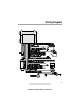
Wiring Diagram 3 AMX78(3) Installation Manual - Revised 0799
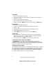
14 Pin Connector Wire Color Description RED/WHITE Parking Light Polarity (+) or (-) Select RED/BLACK Parking Light Output(s) - 2 Wires for European Models RED Battery (+) GRAY Armed (-) Output Pre-wired to Starter Disable Relay BLACK Battery (-) VIOLET Siren (-) Output TAN Hood/Trunk (-) Input WHITE/BLACK Interior Light Trigger/Illumination Polarity (+) or (-) Select DARK BLUE Channel 2 Accessory (-) Output WHITE Door Trigger (+) or (-) Input PINK Ignition Input Prewired to Starter Di
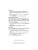
Installation Procedures Control Unit 1. Select a location under the dash that will allow you to use the tie wraps to securely fasten the control unit. 2. Mount the control unit as high as possible to ensure maximum range. 3. Do not mount the control unit near moving parts. 4. Avoid areas that are in the direct path of air blowing from the vents. 5. Route wires from this point, leaving slack for ease of service. Antenna 1. Do not shorten or lengthen the antenna. 2.
Valet Switch 1. Discuss placement with the owner. 2. Choose a location for the valet switch that is hidden, but convenient for the owner to access. 3. Drill a ¼" hole and mount the switch. 4. Route the valet switch wires to the control unit. 5. Plug the valet switch WHITE connector into the control unit WHITE plug. LED Indicator 1. Discuss placement with the owner. 2. Choose a location that is visible from both sides of the vehicle. 3. Drill a ¼" hole. 4.
Parking Lights 1. If the parking lights are positive trigger, connect the RED/WHITE wire to the battery positive (+) terminal through the 20 amp fuse. NOTE: Do not connect the RED/WHITE wire to the control unit RED wire. 2. If the parking lights are negative (-) trigger, connect the RED/WHITE wire to control unit BLACK wire. 3. Connect the RED/BLACK wire to the vehicle parking light wire. Interior Light Trigger/Illumination The system’s door trigger will accept a positive or negative door trigger input.
Hood/Trunk Pin Switch 1. Locate the vehicle hood and/or trunk pin switch that show ground when the hood or trunk is open only. 2. Connect the alarm module to the vehicle hood and/or trunk pin switch wire. 3. If the vehicle does not have a hood or trunk pin switch, install an alarm pin switch and connect it to the alarm module TAN wire. Siren 1. Choose a location in the engine compartment away from high heat engine components, moving parts and direct exposure to water. 2.
Door Lock/Unlock Be sure to verify the type of door lock system you are working with. Some types of door lock systems require optional I CAUTION: relays, for example, reverse polarity type door locks. Refer to the diagrams on pages 8 & 9. The system can operate both negative and positive door locks. When the alarm is remotely armed, the BLUE/WHITE wire provides a negative output. At the same time, the GREEN/WHITE wire provides a 300 MA positive output.
10 Manual
11 Manual
Programmable Features All system and remote control programmable features are accomplished by turning the ignition key to the “ON” position or starting the engine and flicking the valet switch on and off a preset number of times. The siren will chirp for audible programming confirmation. The system also allows the user to add new remote controls in one step, delete lost or stolen remote controls or rearrange the factory preset remote control functions. 1. Remove the system from Protected Valet Mode.
Programming Table for Alarm Features Feature Factory Setting # of Chirps Secondary Action Active/Passive Arming Passive ON 4 Wait 3 seconds, the siren chirps once for Active or twice for Passive. Passive Door Lock OFF 5 Wait 3 seconds, the siren chirps once for OFF or twice for ON. Instant/Delayed Ignition Control Door Lock Delayed 6 Wait 3 seconds, the siren chirps twice for Instant or once for Delayed.
Programming Table for Remote Controls Feature Arm/Disarm/Remote Panic Trunk Output Silent Arm/Disarm Optional Accessory (-) Output Factory Setting # of Chirps Secondary Action 12 Press the ARM/DISARM button. The siren will chirp once for confirmation. 13 Press the TRUNK button. The siren will chirp twice for confirmation. 14 Press the SILENT button. The siren will chirp 3 times for confirmation. 15 Press the OPTION button. The siren will chirp 4 times for confirmation.