
Programming instructions


HomeWorks®/AMX inconcert Processor
HP5-H48-AMX-120 (AMX Model: ALD-H48-AMX-INT)
12 V 60 Hz 30 VA
1
Please Read Before Installing
Overview
The HP5-H48-AMX-120 Processor allows connection of
HomeWorks Wired Keypads and HomeWorks Wired
Maestro
® Local Lighting Controls. The central processor
provides lighting presets and easy integration into an
AMX system.
A maximum of 24 Designer-Style keypads may be
connected to and powered by the Keypad Link on the
HP5-H48-AMX-120 Processor.
Important Notes
Codes: Install in accordance with all local and
national electrical codes.
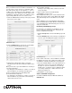
Power: Two separate power inputs exist on this
processor:
1. Processor power is provided by the 2 conductor
harness that is integral to the HWI-LV24 enclo-
sure. The processor is powered when the green
LED labeled “PWR” is on.
2. Connected keypads are powered by the supplied
plug-in adapter connected to the power jack
labeled “Keypad Link 15 V ”. The Keypad Link
is powered properly when the green “Keypad
LINK PWR” LED is on. If the red “LINK SHORT”
LED is on, the Keypad Link is shorted (between
terminal 1 and 2) or overloaded (exceeding 150
LEDs).
Both Processor power and Keypad Link power must
be present for the processor and keypads to function
properly.
Processor Power: 12 V 30 VA
Keypad Link Power: 15 V 900 mA NEC Class 2;
IEC PELV
Use only the adapter provided by Lutron with
the HP5-H48-AMX-120 Processor.
Environment: Ambient operating temperature:
0-40 °C, 32-104 °F, 0-90% humidity, non-condensing.
Indoor use only.
Cleaning: To clean, wipe with a clean damp cloth. DO
NOT use any chemical cleaning solutions.
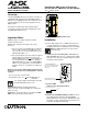
Figure 1 - HP5-H48-AMX-120 Processor
Installation Instructions
1. Ensure High-voltage cover in HWI-LV24 enclosure is
securely installed. Locate and lock supply breaker in
the OFF position before installing processor assembly.
Danger - Wiring with power on may result in
personal injury.
2. Install processor assembly in the enclosure: The
HP5-H48-AMX-120 Processor is attached to the HWI-
LV24 enclosure using four mounting keyholes and the
mounting screws provided.
3. Ensure all DIP
switches are in the down position.
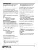
4. Connect to HomeWorks lighting controls. Connect
the communication wiring from the HomeWorks
Maestro Dimmers to the factory installed Dimmer Hub.
See Figure 3, page 2. Gray and violet connections are
marked on the printed circuit board.
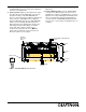
Installation
Figure 2 - Mounting
Diagram
The HP5-H48-AMX-120
Processor mounts in the upper
left corner of an HWI-LV24
enclosure.
High-voltage enclosure
(shown with cover installed).
Down (OFF)
Up (ON)
Example: Setting Switch #6 ON.