Naza-M V2 Quick Start Guide V 1.00 2013.05.02 Revision For Firmware Version V3.10 & Assistant Software Version V2.10 Thank you for purchasing this DJI product. Please strictly follow these steps to mount and connect this system on your aircraft, as well as to install the Assistant Software on your computer. Please regularly check the Naza-M V2 web page at our website www.dji-innovations.com, which is updated regularly.
Index INDEX ...........................................................................................................................................................2 INSTRUCTION ..............................................................................................................................................3 DISCLAIMER & WARNING ..................................................................................................................................... 3 TRADEMARK ....................
Instruction Disclaimer & Warning Please read this disclaimer carefully before using the product. By using this product, you hereby agree to this disclaimer and signify that you have read them fully. THIS PRODUCT IS NOT SUITABLE FOR PEOPLE UNDER THE AGE OF 18. Naza-M V2 is an autopilot system designed for serious multi-rotor enthusiasts providing excellent self-leveling and altitude holding, which completely takes the stress out of flying RC multi-rotors for both professional and hobby applications.
Trademark DJI and Naza-M are registered trademarks of DJI Innovations. Names of product, brand, etc., appearing in this manual are trademarks or registered trademarks of their respective owner companies. This product and manual are copyrighted by DJI Innovations with all rights reserved. No part of this product or manual shall be reproduced in any form without the prior written consent or authorization of DJI Innovations.
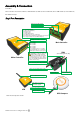
Assembly & Connection In the Box: Main controller X1, PMU X1, GPS X1, GPS Bracket X1, LED X1, Servo Cable X8, Micro-USB Cable X1, CAN Cable X1, 3M Adhesive Tape.
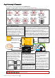
Step2 Assembly & Connection Step1 Prepare an aircraft, supported the following Mixed Types. The direction of the arrow in diagram indicates the rotation direction of the motor/propeller. Important:To coaxial propellers: Blue propeller is at TOP; Red propeller is at Bottom. Otherwise all propellers are at top.
Assistant Software Installation and Configuration Step1 Software and Driver Installation on a PC 1. Please download the drive installer and the assistant software installer from DJI website “www.dji-innovations.com” -> ”PRODUCTS” -> ”Naza-M V2” -> ”SUPPORT”. 2. Switch on the transmitter first, and then power on the autopilot system. 3. Connect the autopilot system and the PC via a Micro-USB cable, and power on the autopilot system. 4.
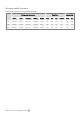
Recommended Parameters Recommended Settings for using F330/F450/F550 Configuration Information Basic Gain Attitude Gain Motor ESC Propeller Battery Weight Pitch Roll Yaw Vertical Pitch Roll F330 DJI-2212 DJI-18A DJI-8 Inch 3S-2200 790 g 140 140 100 110 140 140 F450 DJI-2212 DJI-30A DJI-8 Inch 3S-2200 890 g 150 150 100 105 150 150 F550 DJI-2212 DJI-30A DJI-8 Inch 4S-3300 1530 g 170 170 150 140 170 170 ©2013 DJI Innovations. All Rights Reserved.
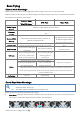
Basic Flying Control Mode Knowledge Please read the Control Mode Knowledge clearly before usage, to know how to control the aircraft. Different control modes will give you different flight performances. Please make sure you understand the features and differences of the three control modes. GPS ATTI. Mode ATTI.
2 Stop Motor: We provide two options to stop motors in the assistant software: Immediately and Intelligent. (1) Immediately Mode: If you select this mode, in any control mode, once motors start and throttle stick is over 10%, motors will not stop immediately only when throttle stick is back under 10% the motors will stop. In this case, if you push the throttle stick over 10% within 5 seconds after motors stop, motors will re-start, CSC is not needed.
Step1 Compass Calibration Without GPS module, please skip this step. If you use with GPS module, follow step-by-step for calibration. (1) DO NOT calibrate your compass where there is magnetic interference, such as magnetite, car park, and steel reinforcement under the ground. (2) DO NOT carry ferromagnetic materials with you during calibration, such as keys or cell phones. (3) Compass module CANNOT work in the polar circle.
Step2 Assembly Checking List Please check each item, to make sure for safety. Any of the following mistakes will lead to a dangerous accident, double check all these items: (1) Rotation direction of motor is opposite (2) Infirm connection between the motor and the ESC (3) Wrong or infirm installation of Main controller (4) Wrong or infirm connection between the main controller and ESC. (5) Propeller installation mistake (6) Magnetization of the compass Make sure the following items are correct.
4. Keep the aircraft stationary, and then push both sticks to the left bottom or right bottom (shown as the following chart, defined as Combination Stick Commands (CSC)), to start the motors. 5. Release the yaw, roll and pitch sticks and keep them at the neutral position, and the throttle stick under the neutral position. Then check whether all propellers are rotating correctly. 6.
4. Lower the aircraft slowly. Pull the throttle stick to the bottom and then execute the CSC to stop the motors after landing. 5. Please always power off the Multi-rotor first, and then switch off the transmitter after landing. FLYING NOTES(VERY IMPORTANT)! ! ! (1) If you enable the Immediately Mode of Motor Stop; you should not pull throttle stick under 10% during flight, because it will stop motors. If you do it accidentally, you should push the throttle stick over 10% in 5s to re-start motors.
Advanced Functions A1 FailSafe An introduction of Go-Home and Landing.
A2 Low-Voltage Alert In order to prevent your multi-rotor from a crash or other harmful consequences caused by low battery voltage, there are two levels of low voltage protection available to use. You can choose to use or not to use them; however we strongly recommend using the protections available! Low-Voltage Alert is to indicate that the battery cannot provide enough power for the aircraft, in order to warn you to land the aircraft ASAP.
A3 Intelligent Orientation Control (IOC) Flight (with GPS module) Definition of Forward Direction: Multi -rotor will fly along this direction when you push the elevator stick ( ). Step1 Before You Start Usually, the forward direction of a flying multi-rotor is the same as the nose direction. By using IOC, wherever the nose points, the forward direction has nothing to do with nose direction. The red and blue arrows on the transmitter are corresponding to pitch and roll operations in the following diagram.
Step3 Method of Forward Direction and Home Point Recording If you use the IOC function, please be aware of the Forward Direction of Course Lock Flying, and the home point of Home Lock Flying. There are two ways to record the forward direction and the home point: Manually and Automatically. You may choose any one record method. The LED will blink Green quickly if successfully recorded.
IOC FLYING NOTES! ! ! (1) When Multi-rotor is flying by home lock far away from you and the home point, please DO NOT toggle the IOC switch many times quickly so as to avoid the change of home point without your attention. (1) Home lock flying requires that 6 or more GPS satellites are found and the aircraft is further than 10m away from the home point. (2) If the IOC flying requirement is not satisfied, the autopilot system will quit IOC control mode.
Appendix Specifications General Built-In Functions (1) Three Modes of Autopilot (4) S-Bus Receiver Support (2)Enhanced Fail Safe (5)PPM Receiver Support (3)Low Voltage Protection (6) 2-axle Gimbal Support Peripheral Supported Multi-rotor Quad-rotor I4, X4; Hexa-rotor I 6, X6, IY6, Y6. Octo- rotor I8, V8, X8 Supported ESC output 400Hz refresh frequency. Recommended Transmitter PCM or 2.4GHz with a minimum 4 channels.
MC/PMU Firmware Upgrade Please follow the procedure for software and firmware upgrade; otherwise the system might not work properly. For SAFETY REASONS, DO NOT use power battery during firmware upgrade. 1. Make sure your computer is connected to the Internet. 2. Please close all the other applications during the firmware upgrade, including anti-virus software and firewall. 3. Make sure the power supply is securely connected. DO NOT un-plug the power supply until firmware upgrade has finished. 4.
LED Description System Status LED Flashing System start and self-check IMU abnormal data Warm up after power on Bias of Sensors too Big Compass Error too Big Tx signal lost Low Voltage Alert Record forward direction or home point Manual Mode: None Control Mode Indictor ATTI.
Instruction of V1 V1 system is different from V2system, if you are V1 system user, please read the following text carefully. V1 Assembly and Connection Connect the V1 system according to the following chart, and refer to the above text (V2) for configuration and testing details. VU R/C System · These are example connections.
V1 Port Description Please remember the function of each port, which may help you to use the Naza-M efficiently.
V1 Specification General Built-In Functions Three Modes of Autopilot Enhanced Fail Safe Low Voltage Protection S-Bus Receiver Support PPM Receiver Support 2-axle Gimbal Support Quad-rotor I4, X4; Hexa-rotor I 6, X6, IY6, Y6. Peripheral Supported Multi-rotor Supported ESC output 400Hz refresh frequency. Recommended Transmitter PCM or 2.4GHz with a minimum 4 channels.
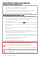
FAQ Abnormal LED Indication List During the Checking Procedure, if abnormal LED Indicator occurs or even the system cannot work normally, please refer to the following list and aids troubleshooting. (1) “System initializing and self-checking LED flashes” are not correct ( Red LED appears in the last four green flashes). The autopilot system works abnormally. Please contact your dealer. (2) LED blinks Yellow 4 times quickly ( ). The system is warming up.
counter-clockwise direction, please re-mount the GPS module correspondingly. is the rotating direction of aircraft, is the nose direction of aircraft, is the arrow direction on the GPS module, θ is the offset angle for GPS re-mounting(about 10~30o) Clockwise rotating GPS re-mounting Counter Clockwise rotating GPS re-mounting θ Should you find the multi-rotor does not track straight in forward flight, Please carry out several more courses, the system will fix it automatically. ©2013 DJI Innovations.