
Instruction manual

Product Overview and Specifications
16
Instruction Manual – DXLink™ Twisted Pair Transmitters/Receiver
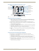
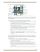
DXLink Multi-Format Wallplate TX (DX-TX-WP) Front View
Components located on front of Wallplate TX:
HDMI In – HDMI connector (with locking center screw) for digital video and embedded digital audio
(supports a DVI-D signal with use of DVI-to-HDMI cable adapter). When more than one audio signal is
present, HDMI embedded audio takes precedence over analog audio.
Digital Video LED – Indicates the unit is configured to pass HDMI with embedded audio (default).
Video In – An HD-15 connector for analog video: C (composite), Y/C, Y/Pb/Pr, RGB, RGBHV, or RGBS.
Pinouts for analog video are on page 124.
Analog Video LEDs – Illuminates when the Wallplate TX is configured to pass analog video: composite or
Y/C; Y/Pb/Pr or RGB; RGBHV or RGBS.
Audio In Stereo – Audio connector is a 3.5 mm stereo jack. An analog audio signal is only available when
HDMI embedded digital audio is not present (or configured for analog audio).
Audio LED – Indicates the unit is configured to pass analog audio (coupled with digital or analog video
path).
USB Host port – Mini-B USB connector (supports USB host) for receiving keyboard / mouse commands
from a specific RX. (For USB port information, see page 26.)
Power LED – Indicates when the Wallplate TX is powered on.
Components located on left and bottom edges of Wallplate TX:
Reset button (left) – Resets the Wallplate TX’s CPU (acts like a power cycle soft reboot).
Program port (left) – This port (USB mini-B connector) supports DGX Configuration Software for
programming a customer VGA EDID.
ID Pushbutton (left) – Places the Wallplate TX in ID Mode for setting the NetLinx ID (device only) and
provides additional functionality, such as placing the device in Static IP Mode or DHCP Mode.
NetLinx LEDs (bottom) – Left green LED (L = Link/Act) indicates network communication activity; right
green LED (S = Status) indicates unit status
.
DXLink LEDs (bottom) – Left yellow LED indicates HDCP status; right green LED indicates that a valid
DXLink connection has been established.
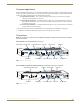
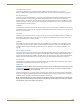
FIG. 3 Multi-Format Wallplate TX front view, plus left edge and bottom edge views
Left edge
Reset button
Program port
ID Pushbutton
Analog Video LEDs
HD-15 Input
Digital Video LED
Audio LED
HDMI Input
USB Host
Stereo Audio Input
Power LED
DXLink LEDs
Bottom edge
NetLinx LEDs