
Instruction manual


Appendix D – Cable Details and Pinout Info
124
Instruction Manual – DXLink™ Twisted Pair Transmitters/Receiver
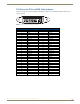
HD-15 Connector Cable Pinout
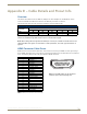
HD-15 connectors are found on the Multi-Format TX, Wallplate TX, and Decor Wallplate TX. These connectors are
used to accept a variety of analog video signals from a source device. The following table provides cable pinout details
for HD-15 connections for VGA, VGA-RGBS, VGA-RGsB, component, S-Video, and composite.
HD-15 Connector Cable Pinout
Input Pin # VGA-RGBHV VGA-RGBS VGA-RGsB Component S-Video Composite
1Red Red Red Pr n/c n/c
2 Green Green Green+Sync Y Y Composite
3 Blue Blue Blue Pb C n/c
4 n/c n/c n/c n/c n/c n/c
5 GND GND GND n/c n/c n/c
6 GND - Red GND - Red GND - Red GND - Pr n/c n/c
7 GND - Green GND - Green GND - Green GND - Y GND - Y GND - Composite
8 GND - Blue GND - Blue GND - Blue GND - Pb GND - C n/c
9 +5 V DDC +5 V DDC +5 V DDC n/c n/c n/c
10 GND GND GND n/c n/c n/c
11 n/c n/c n/c n/c n/c n/c
12 DDC_SDA DDC_SDA DDC_SDA n/c n/c n/c
13 H Sync S n/c n/c n/c n/c
14 V Sync n/c n/c n/c n/c n/c
15 DDC_SCL DDC_SCL DDC_SCL n/c n/c n/c
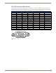
FIG. 42 HD-15 Connector pins