
User Guide


Installation and Wiring
4
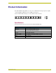
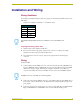
ABS AXlink Bus Strip
For additional information about the wiring distances between the ABS and a specific AXlink
device, refer to the appropriate manual.
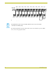
FIG. 2 ABS wiring diagram
GND
PW
R
GND -
(
BLK
)
AXP
(
WHT
)
AXM
(
GRN
)
PWR + (RED)
GND -
(
BLK
)
AXP
(
WHT
)
AXM
(
GRN
)
PWR + (RED)
AXlink
Device 9
AXlink
Device 8
Control
System
AXlink
Device 7
AXlink
Conn. 1
AXlink
Conn. 2
AXlink
Conn. 3
AXlink
Conn. 4
AXlink
Conn. 5
AXlink
Conn. 10
AXlink
Conn. 9
AXlink
Conn. 6
AXlink
Conn. 7
AXlink
Conn. 8
AXlink
Device 4
AXlink
Device 3
AXlink
Device 1
AXlink
Device 5
AXlink
Device 6
AXlink
Device 2
System
Power
Supply
Power
Conn.
If the AXlink devices have local power supplies, do not connect to the power terminal
of the ABS via the PWR+ (Red).