
User Guide


Installation and Wiring
3
ABS AXlink Bus Strip
Installation and Wiring
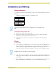
Wiring Guidelines
To determine the maximum distance allowed per gauge, use the following formula and refer to the
table below:
1.5/(Power Consumption x Resistance x 2) = Distance (feet)
Preparing/connecting captive wires
1. Strip 0.25 inch of wire insulation off all wires.
2. Insert each wire into the appropriate opening on the connector according to the wiring
diagrams and connector types described in this section.
3. Do not tighten the screws excessively; doing so may strip the threads and damage the
connector.
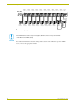
Wiring
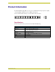
To wire the ABS:
1. Connect wiring from the AXlink devices to connectors 2 through 10 on the ABS (FIG. 2). If
the power LED lights when an AXlink cable is connected to the ABS, it indicates the AXlink
cable has a local power supply. Unless that local supply is intended to power all devices
connected to the ABS, disconnect it and insulate the wire connected to the PWR+ terminal.
2. Connect the control system AXlink connector 1 on the ABS. As with the other AXlink devices
in the system, connect all four wires to the ABS unless the Central Controller is using a local
power supply.
3. Connect the system power supply to the 2-pin connector on the ABS. The power LED should
light, and all AXlink devices with PWR+ connected to the ABS should have power.
Wiring Guidelines
Gauge Resistance
18 AWG .00639
20 AWG .0101
22 AWG .0162
24 AWG .0257
The maximum wiring lengths are based on a minimum of 13.5 volts available to the
ABS.
All AXlink connectors on the ABS are connected together.