instruction manual ABS AXlink Bus Strip C on t ro l S y s t em A c c e s s or ie s
AMX Limited Warranty and Disclaimer AMX Corporation warrants its products to be free of defects in material and workmanship under normal use for three (3) years from the date of purchase from AMX Corporation, with the following exceptions: • Electroluminescent and LCD Control Panels are warranted for three (3) years, except for the display and touch overlay components that are warranted for a period of one (1) year.
Table of Contents Table of Contents Product Information .................................................................................................1 Specifications .................................................................................................................... 1 Installation and Wiring .............................................................................................3 Wiring Guidelines ....................................................................................
Table of Contents ii ABS AXlink Bus Strip
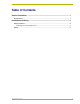
Product Information Product Information The ABS AXlink Bus Strip (FIG. 1) is a 10-connector AXlink terminal strip designed to simplify connecting multiple AXlink devices in an AMX Control System. Use the included double-sided tape to securely affix the unit to the surface. FIG. 1 ABS Axlink Bus Strip Specifications The following table lists the specifications for the ABS Axlink Bus Strip. Specifications Power Connectors 12 VDC, 7 A max.
Product Information 2 ABS AXlink Bus Strip
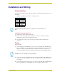
Installation and Wiring Installation and Wiring Wiring Guidelines To determine the maximum distance allowed per gauge, use the following formula and refer to the table below: 1.5/(Power Consumption x Resistance x 2) = Distance (feet) Wiring Guidelines Gauge Resistance 18 AWG .00639 20 AWG .0101 22 AWG .0162 24 AWG .0257 The maximum wiring lengths are based on a minimum of 13.5 volts available to the ABS. Preparing/connecting captive wires 1. Strip 0.25 inch of wire insulation off all wires. 2.
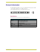
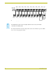
Installation and Wiring AXlink Conn. 10 AXlink Conn. 9 AXlink Conn. 8 AXlink Conn. 7 AXlink Conn. 6 AXlink Conn. 5 AXlink Conn. 4 AXlink Conn. 3 AXlink Conn. 2 AXlink Conn. 1 Power Conn. PWR + (RED) AXP (WHT) PWR GND AXM (GRN) GND - (BLK) AXlink Device 9 AXlink Device 8 AXlink Device 7 AXlink Device 6 AXlink Device 5 AXlink Device 4 AXlink AXlink Device 3 Device 2 AXlink Device 1 Control System System Power Supply FIG.
Installation and Wiring ABS AXlink Bus Strip 5
brussels • dallas • los angeles • mexico city • philadelphia • shanghai • singapore • tampa • toronto • york 3000 research drive, richardson, TX 75082 USA • 469.624.8000 • 800.222.0193 • fax 469.624.7153 • technical support 800.932.6993 041-004-1561 8/01 ©2001 AMX Corporation. All rights reserved. AMX, the AMX logo, the building icon, the home icon, and the light bulb icon are all trademarks of AMX Corporation. AMX reserves the right to alter specifications without notice at any time.