
Specifications


RMa750 Programming Definitions Monday, 10 July 2000
page 7
Channels 13 and 16 of the CNPI/ CPI are not currently being used.
A.C. Fault Detect Reset. (normally high)
Channel 14 is used to reset the micro on the interface. The micro will latch an input relative to the
channel reporting an input to output fault. To enable the operator or program to verify a sustained
fault condition, a reset has been included to reset the micro so as to un-latch all inputs and re-start
the interrogation program of the micro. Sending this output low will reset all channels of the
applicable amplifier. This is to be a momentary action only as holding this pin low overides the
micro on the amplifier to control system interface.
Input to output faults should be interrogated/verified with the offending channel’s relay open (so as
not to kill your load in case it is a really big fault). I.E. If a in/out fault is reported, force the channel
relay open (to override the resetting of the relay), reset the amplifier and see if the fault occurs
again, if not, close the relay - you don’t even have to leave your chair.
Remote Power.
Channel 15 has been assigned to provide the control
signal to initiate a remote “MAINS” power up
of the amplifier. If the amplifier has been enabled for remote power up/down by engaging the rear
panel switch then channel 15 going low will turn the amplifier on. Channel 15 going high will turn
the amplifier off. Channel 15 controls a mains switching relay which is powered by the control
system network. A LED on the front panel of the amplifier indicates that remote power has been
enabled and this is reflected at the control screen via input channel 15 as well. The front panel
mains on/off switch on the amplifier will override the remote system for power on if it is in the
“ON” position.
If the “UNIT-READY” input is low (input channel 16) then if the “remote power on” has not been
selected but the amplifier has been manually turned on via the front panel switch, the remote power
indicator should be ignored in some way.
Obviously there will be numerous questions and “what ifs” arise from the above. Various input
from all parties involved will ultimately create your final program.
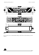
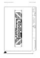
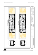
3 drawings have been included with this communique which show the layout and legends of the
front and Back panels along with an installation drawing showing major dimensions.
Due to the extended class-A MOSFET output stage of the RMa750, the quiescent (idle) mains
current draw is about 1 Amp, the mains fuse is rated at 5 amps and current peaks over 8 amps can
be produced. The unit is a 2RU 19” rack mounting unit. Mains termination is via a standard IEC
connector, all inputs are 3 pin female XL type connectors where Pin-2 = Hot. Speaker termination
is via a heavy duty 3/4” (19mm) spaced binding posts which will accept cable up to 4mm
2
.
Yours Sincerely,
Stuart McLean.
Design & Product Engineer.
engineering@audiotelex.com.au www.audiotelex.com.au www.australianmonitor.com.au