
Specifications


RMa750 Programming Definitions Monday, 10 July 2000
page 3
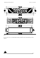
and the in line female plug is a: MSTB 2.5/4-ST-5.08
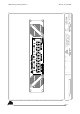
Due to these companies wanting to look a little bit different, the wiring for the AXlink buss and the
Crestnet buss is exactly opposite. To avoid adding extra cost and dedicated panels for each system
we have included both wiring legends on the back panel and the orientation of the connector
displays the appropriate legend.
Above the connector is a field where the ADDRESS / ID CODE of each amplifier will be marked.
As the Custom panel interface cards are internally fitted we need to set these address’s / codes
during manufacture of the RMa units. Please provide us with this information at your earliest.
A spreadsheet (RMa_PROG.XLS) of operational and control parameters is attached to aid
programming of the system.
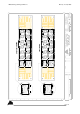
Channel assignments re CNPI/ CPI cards.
NOTE: High = off and Low = on.
INPUTS
Input to Output faults (normally high)
Channels 1 to 6 monitor Input to Output faults.
Channel 1 = Channel 1 of the amplifier
Channel 2 = Channel 2 of the amplifier
Channel 3 = Channel 3 of the amplifier
Channel 4 = Channel 4 of the amplifier
Channel 5 = Channel 5 of the amplifier
Channel 6 = Channel 6 of the amplifier
The amplifier’s interface simply monitors that the input to output gain and signal integrity is the
same. If it is to vary then the CNPI/ CPI input for the offending channel will flag the system. The
in/out detector will show any fault including, D.C quiescent faults (post pre-amp), D.C. on the
output, Oscillation, abnormally high noise (that is not input born), a muted amplifier, various circuit
failures, bad connections, clipping etc,etc. The circuit is not sensitive to gain alteration via the front
panel attenuator. An input to output fault has to be maintained before the system is flagged. This is
accomplished by oversampling by the internal micro which will then latch the offending channels
CNPI/ CPI input. An input to output fault should automatically disconnect the offending channel.
This can be accomplished two ways.
1) The system is alerted to the fault and takes action by opening the offending channels
output speaker relay,
or
2) The system is alerted to the fault but the amplifier has automatically opened the relay of
the offending channel.