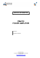
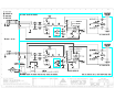
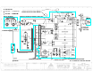
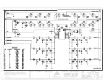
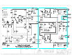
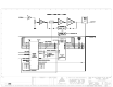
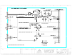
SERVICE INFORMATION RMa750 POWER AMPLIFIER CONTENTS: SCHEMATIC DIAGRAMS Australian Monitor 1 Clyde Street, Silverwater NSW 2128 Australia +61 2 9647 1411 www.australianmonitor.com.
149 Beaconsfield Street, Silverwater. NSW 2128 Phone: 61 2 9647 1411 Fax: 61 2 9748 2537 RMA750 Overview Following is an overview of the RMa750 6 channel amplifier including installation and programming aspects when using: 1) CRESTRON CNPI/ CPI-16B Custom Panel Interface card. 2) AMX AXP-CPI16 Custom Panel Interface card. These cards are able to accept up to 16 inputs from the amplifier and the cards also have 16 outputs which can be used to control a number of aspects of the amplifier.
RMa750 Programming Definitions Monday, 10 July 2000 as an early warning system as well. A fault from the in/out detect circuit will pass through an internally selectable link which will either have the amplifier disconnect the offending channels relay or have the program (via the control system) open the output relay of the offending channel.
RMa750 Programming Definitions and the in line female plug is a: Monday, 10 July 2000 MSTB 2.5/4-ST-5.08 Due to these companies wanting to look a little bit different, the wiring for the AXlink buss and the Crestnet buss is exactly opposite. To avoid adding extra cost and dedicated panels for each system we have included both wiring legends on the back panel and the orientation of the connector displays the appropriate legend.
RMa750 Programming Definitions Monday, 10 July 2000 A 2 pin header on the amplifier interface is utilised to select which option is appropriate. We will be supplying the units with a header link in place which will have the amplifier automatically open the relay. Once a fault is detected the CNPI/CPI input is held/latched low. The input will remain in this state until a reset from the control system is detected (via channel 14 on CNPI/.CPI output).
RMa750 Programming Definitions Monday, 10 July 2000 Remote Power Select. Channel 15 is used to indicate to the system that the rear panel switch on the amplifier has been engaged to enable remote power up / power down of the amplifier. High = not selected / not enabled, Low = selected / enabled. This feature is powered by the Crestnet/AXlink network. The switch on the back panel will do several functions.
RMa750 Programming Definitions Monday, 10 July 2000 OUTPUTS. Channel Mutes (normally high and thus un-muted) Channels 1 to 6 act as mute control. Channel 1 = Channel 1 of the amplifier Channel 2 = Channel 2 of the amplifier Channel 3 = Channel 3 of the amplifier Channel 4 = Channel 4 of the amplifier Channel 5 = Channel 5 of the amplifier Channel 6 = Channel 6 of the amplifier Sending these channels low will mute the appropriate amplifier channel.
RMa750 Programming Definitions Monday, 10 July 2000 Channels 13 and 16 of the CNPI/ CPI are not currently being used. A.C. Fault Detect Reset. (normally high) Channel 14 is used to reset the micro on the interface. The micro will latch an input relative to the channel reporting an input to output fault. To enable the operator or program to verify a sustained fault condition, a reset has been included to reset the micro so as to un-latch all inputs and re-start the interrogation program of the micro.
RMa750 Programming Definitions Monday, 10 July 2000 Note: Level control is via a tool adjust flush mounted pot shaft. The end of the shaft has a position indicator.
RMa750 Programming Definitions Monday, 10 July 2000 page 9
RMa750 Programming Definitions Monday, 10 July 2000 page 10
Operation/Reference Guide AXP-CPI16 16-Channel Custom Panel Interface Custom Panel Interfaces Document ID: 038-004-1334 Last Revised: 8/16/2006
AMX Limited Warranty and Disclaimer AMX warrants its products to be free of defects in material and workmanship under normal use for three (3) years from the date of purchase from AMX, with the following exceptions: • Electroluminescent and LCD Control Panels are warranted for three (3) years, except for the display and touch overlay components that are warranted for a period of one (1) year.
Table of Contents Table of Contents Product Information ...........................................................................................1 Specifications............................................................................................................ 1 Installation ..........................................................................................................5 Mounting Dimensions ...............................................................................................
Table of Contents ii AXP-CPI16 16-Channel Custom Panel Interface
Product Information Product Information The AMX AXP-CPI16 16 Channel Custom Panel Interface Board (FIG. 1) simplifies the process of creating custom control panels for Axcess systems. Providing contact closure inputs and feedback outputs for up to 16 buttons, the miniature PC board contains a 20-pin header for ribbon cable installation or for direct mounting to a printed circuit board.
Product Information AXP-CPI16 Specifications (Cont.) AXlink Status LED Indicates AXlink communication status as follows: • One blink per second communication is functioning. • Two blinks per second devices specified in the master program do not match the specified devices found. • Three blinks per second indicate an AXlink communication error. • Full-on indicates there is no AXlink control or activity (but power is on), or the Axcess program is not loaded.
Product Information OFF OFF ON ON AXP-CPI16 16-Channel Custom Panel Interface 1 2 3 4 5 6 7 8 3
Product Information 4 AXP-CPI16 16-Channel Custom Panel Interface
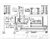
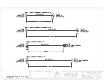
Installation Installation Mounting Dimensions LH B B AA A A C C AXlink AXlink GND PWRAXP AXP AXM GND L J P1 1 1 22 P1 PWR AXM P3 P3 Top View (Component Side) Top View (Component Side) D D E E P2 P2 2 1 19 19 20 20 MM 20 20 19 19 J G F F KG H K min min FIG. 1 AXP-CPI16 mounting dimensions Mounting Dimensions Item Inch mm Item Description A 0.10 2.50 K B 1.75 44.50 L 0.125 Inch (3.2 mm) mounting holes for #4-40 (3 mm) screws C 1.55 39.40 M P3 20-Pin Header .
Installation Setting the AXlink Device Number The 8-position device DIP switch defines the AXP-CPI16 as an AXlink device. It can be one of 255 devices in the Axcess Control System. Set the device number with the total value of all ON (down) positions. As an example, the device DIP switch shown below defines device number 129 (1+128=129). Position 1 2 3 4 5 Value 6 7 8 OFF OFF 1 2 4 8 16 32 64 128 ON ON 1 2 3 4 5 6 7 8 AMX standard device numbers are assigned as follows: Cards are 1 through 25.
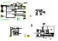
Installation Switch Wiring Diagrams FIG. 2 diagrams LED and Switch wiring. LED Wiring (Typical) 10 LED 1 1K LED 2 1K LED 3 1K Switch Wiring (Typical) SW 1 1 2 12 3 SW 2 SW 3 13 14 15 FIG. 2 LED and switch wiring diagrams Connecting the AXlink Wiring To install the AXlink data/power bus wiring. 1. Strip 0.25 inch off the wire insulation for all four wires. If the wire is 20 AWG or less, fold the exposed wire over to obtain a positive connection. 2.
Installation 8 AXP-CPI16 16-Channel Custom Panel Interface
Programming Programming Use the same Axcess commands as with other AXlink control panels, such as the AXU-MSP series mini-softwire panels. When using the AXP-CPI16 as a control device, use On, Off, and Pulse commands to control sources connected to outputs and Push and Release commands to receive inputs. For additional information, refer to the Axcess Programming Language instruction manual. Send_Commands Command Description Causes the AXP-CPI16 to be in Status-On Mode.
Programming Testing the Unit If you have programmed the Axcess software, load the program into a PC connected to the control system Master port. See Programming on page 4. 1. Push switches connected to the AXP-CPI16. 2. Look at the lower left of the Axcess screen to verify that the correct device and channel numbers are displayed. 3. Check for the appropriate feedback (as provided by the Master Controller program).
AXP-CPI16 System Worksheet AXP-CPI16 System Worksheet Dealer ID Date Dealer PO Number Job SO Number Description Serial Number Rev Number Device Number HEADER P2 Channel 1 2 3 20-PIN HEADER 1 13 2 14 3 15 4 4 5 16 5 17 6 6 7 18 7 19 8 8 20 In In Out Out In In Out Out In In Out Out In In Out Out In In Out Out In In Out Out In In Out Out In In 9 N/C N/C 11 N/C N/C 10 +12 VDC PWR +12VDC PWR 12 PinNumber Number Pin FUNCTION Out Out GND GND AXP-CPI16 16-Channel Custom Panel Inte
AXP-CPI16 System Worksheet HEADER P3 Channel 9 10 11 1 13 2 14 3 15 4 12 16 13 17 5 6 14 15 18 7 19 8 16 20 20-PIN HEADER FUNCTION Out Out In In Out Out In In Out Out In In Out Out In In Out Out In In Out Out In In Out Out In In Out Out In In 9 N/C N/C 11 N/C N/C 10 +12 VDC PWR +12VDC PWR 12 GND GND Pin Number Pin Number 12 AXP-CPI16 16-Channel Custom Panel Interface
System Worksheet AXP-CPI16 16-Channel Custom Panel Interface 13
It’s Your World - Take Control™ 3000 RESEARCH DRIVE, RICHARDSON, TX 75082 USA • 800.222.0193 • 469.624.8000 • 469-624-7153 fax • 800.932.6993 technical support • www.amx.com 038-004-0334 8/06 ©2006 AMX. All rights reserved. AMX and the AMX logo are registered trademarks of AMX. AMX reserves the right to alter specifications without notice at any time.