
User Guide


Installation
12
10.4" Touch Panels
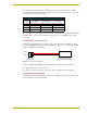
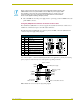
Using the VGA IN HD-15 (male) high-density connector
Connect the VGA source equipment’s HD-15 (female) connector to the VGA IN HD-15 (male)
high-density connector on the rear panel of the touch panel. The table below lists the VGA IN
HD-15 connector pinouts.
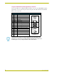
VGA IN HD-15 Connector Pinouts
Pin Signal Function
1 Red Red signals
2 Green Green signals
3 Blue Blue signals
4 N/A Not used
5 GND Signal Ground
6 RAGND Red analog ground
7 GAGND Green analog ground
8 BAGND Blue analog ground
9 N/A Not used
10 SAGND Synchronization analog ground
11 N/A Not used
12 N/A Not used
13 HSYNC Horizontal synchronization signal
14 VSYNC Vertical synchronization signal
15 N/A Not used
VGA HD-15 (male)
connector
10
6
5
1
15
11
CG10 panels are capable of receiving a VGA signal. These VGA signals can be
displayed on a touch panel as a background image and NOT within a video button.
An RGB signal can only be displayed within a Video WIndow Button.