
User Guide


Installation
11
10.4" Touch Panels
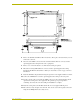
4. Place the PWR wire from the power supply into the open clamp position for PWR on the touch
panel AXlink connector.
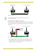
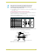
Using the (DB9) RS-232 connector for mouse control or data
The dual-function (DB9) RS-232 connector supports most standard serial mouse control devices
and RS-232 communication protocols for PC data transmission.
The following table lists (DB9) RS-232 connector pinouts and FIG. 9 shows the (DB9) RS-232
connector and power supply wiring diagram.
Use connector pins 2, 3, and 5 for data and ground. For some applications, you may need to strap
pins 7 (request to send) and 8 (clear to send) together, depending on the PC.
Never connect both power wires from the power supply and Central Controller to the
PWR terminal on the touch panel AXlink connector. Only the power supply’s PWR
wire should be connected to the touch panel AXlink connector. If both sources are
used to provide power to the touch panel, an electrical hazard is created and the
threat of both equipment damage and injury is likely.
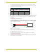
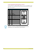
(DB9) RS-232 Connector Pinouts
Pin Signal Function
1 N/A Not used
2 RXD Receive data
3 TXD Transmit data
4 DTR Data terminal ready (not used)
5 GND Signal ground
6 DSR Data set ready (not used)
7 RTS Request to send (not used)
8 CTS Clear to send (not used)
9 N/A Not used
FIG. 9 DB9 RS-232 connector and power supply wiring diagram
9
8
7
6
5
4
3
2
1
9
8
7
6
Female
Male
Power connector
Mouse or PC, DB9 connector
Female
Male
Touch panel
DB9 connector
Optional 7 to 8-pin
connector
2 (RXD)
3 (TXD)
5 (GND)
2 (RXD)
3 (TXD)
5 (GND)
+ (PWR)
- (GND)
12 VDC power supply