
User Guide


Installation
10
10.4" Touch Panels
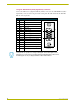
Using AXlink for data with a +12 VDC power supply
To use the AXlink 4-pin connector for data communication with the Central Controller and power
transfer from a power supply, the incoming PWR and GND cable from the power supply must be
connected to the AXlink cable connector going to the touch panel. FIG. 8 shows the external power
supply diagram.
1. Unscrew the PWR and GND wires on the terminal end of the power supply’s 2-pin cable.
2. Pair the GND wires from the power supply and the Central Controller AXlink connectors
together; insert them into the clamp position for GND on the touch panel AXlink connector.
3. Tighten the clamp and secure the two GND wires.
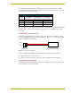
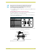
FIG. 7 AXlink wiring diagram
PWR +
AXP/TX
AXM/RX
GND -
To the touch panel
To the external Central Controller
AXlinx/PWR connector
PWR +
AXP/TX
AXM/RX
GND -
Top vi ew
Top view
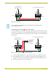
If you are using power from AXlink, disconnect the wiring from the Central Controller
before wiring the touch panel.
FIG. 8 AXlink and external 12 VDC power supply wiring diagram
PWR (+)
GND (-)
Local +12 VDC
(coming from
PWR +
AXP/TX
AXM/RX
GND -
To the touch panel
To the external Central Controller
AXlinx/PWR connector
PWR +
AXP/TX
AXM/RX
GND -
power supply
the PSN
power supply)
To p vi ew
Top view