
Troubleshooting guide

User Lockout
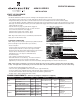
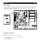
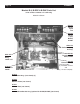
User Lockout is achieved via the position of the LOCK jumper on the board header. Locate the header on the board
(shown below) and place the jumper in the desired position. In the Locked position all menus in this document are
locked out, and the unit will only allow brewing or grinding functions. There are two versions of the header, 10 pin
and 2 pin. Both configurations are shown below.
User Lockout Jumper
User
Lockout
Jumper
Locked
Unlocked
LOCK
LOCK
2 Pin Version
B-SERIES Page 5
Controller Fuse Sizes
Fuses
Controller (pn A530-059) uses (2) 5mm x 20mm 5 Ampere fuses.
Controller (pn A530-056) uses (2) fuses - 1.25” x 0.25” 3AG series 312.
- (1) is a 1 Ampere 3AG-1
- (1) is a 5 Ampere 3AG-5