
User Manual

19
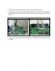
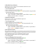
7. Plug the RJ45 white connector to the RJ45 daughter board connector.
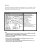
8. Plug the print server module interface cable to connector J1A and J1B on the PCB, the
left side harness (with red wire at the left side) is for J1A, the right side harness location is
for J1B.
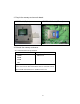
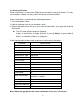
M5 DT Model M5 DT PLUS Model
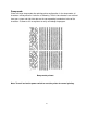
9. Plug the 2 PIN connector on PCB JP26 (M5 DT ) / JP22 (M5 DT PLUS) connector for 5V
DC power.