Fastmark M6 PLUS Series Thermal Transfer Barcode Printer User’s Guide February i 2012 Document #120650
Copyright Information ©2012 AMT Datasouth Corporation The copyright in this manual, the software and firmware in the printer described therein are owned by the printer manufacturer, All rights reserved. CG Triumvirate is a trademark of Agfa Corporation. CG Triumvirate Bold Condensed font is under license from the Monotype Corporation. Windows is a registered trademark of Microsoft Corporation. All other trademarks are the property of their respective owners.
Agency Compliance and Approvals CE CLASS A EN 55022:2006 +A1:2007 EN 55024:1998+A1:2001+A2:2003 EN 61000-4 SERIES REQULATIONS FCC CFR Title 47 Part 15 Subpart B:2009-Section 15.107 and 15.109 ICES-003 Issue 4:2004 Class A AS/NZS CISPR 22:2009 CLASS A GB4953-2001 GB9254-2008 (CLASS A) GB17625.1-2003 此为 A 级产品,在生活环境中,该产品可能会造成无线电干扰,在这种 情况下,可能需要用户对干扰采取切实可行的措施。 UL 60950-1(2nd Edition) CSA C22.2 No.
iv
Contents 1. Introduction ....................................................1 1.1 Product Introduction ................................................................................................ 1 1.2 Product Features ...................................................................................................... 2 1.2.1 Printer standard features ......................................................................... 2 1.2.2 Printer optional features ...........................................
3.1.4 Ethernet ................................................................................................... 55 3.2 File Manager ............................................................................................................ 58 3.2.1 File List .................................................................................................... 58 3.2.2 Avail. Memory ......................................................................................... 59 3.2.3 Del. All Files ...........
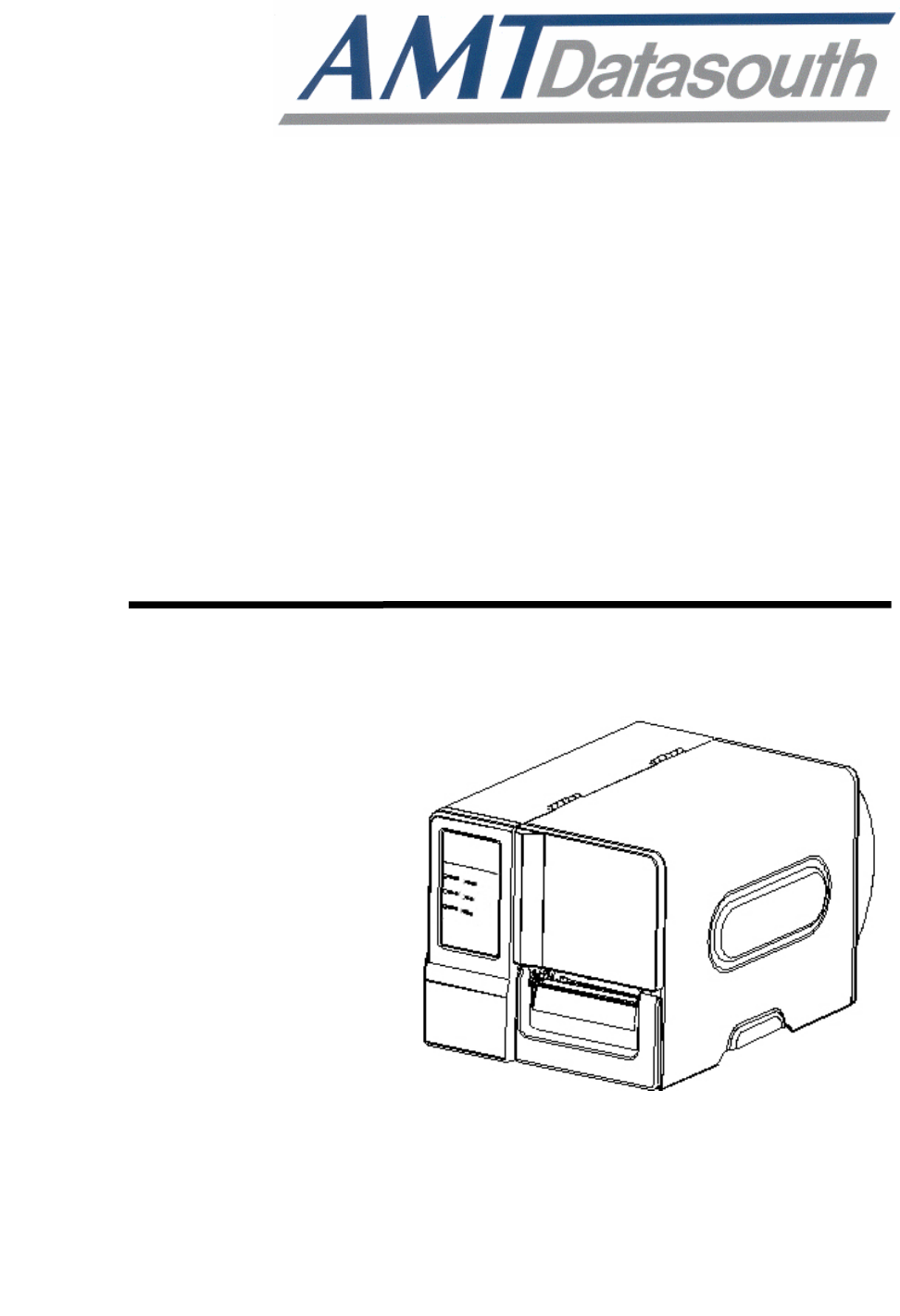
1. Introduction 1.1 Product Introduction Thank you very much for purchasing your bar code printer. Fastmark M6 PLUS series of industrial thermal label printers is designed to offer the right features at the best value in the industry. The M6 PLUS series features a small footprint and low profile design that fits where larger industrial printers do not. It’s quiet operation and fast label throughput is equally at home, in the office or shop floor environment.
1.2 Product Features 1.2.1 Printer standard features The printer offers the following standard features.
Internal Monotype Imaging® true type font engine z z z z z z z z with one CG Triumvirate Bold Condensed scalable font Downloadable fonts from PC to printer memory Downloadable firmware upgrades Text, bar code, graphics/image printing (please ask your reseller about PAL programming for specific applications and print requirements). Supported bar code 1D bar code Code 39, Code 93, Code128UCC, Code128 subsets A.B.
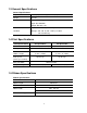
1.3 General Specifications General Specifications Physical dimensions 11.3 in (W) x 10.2 in (H) x 17.1 in (D) Weight 24.3 lbs Electrical Internal switching power supply Input: AC 100-240V Output: DC 24V 3.3A Environmental Operation: 5 ~ 40˚C (41 ~ 104˚F), 25~85% non-condensing condition Storage: -40 ~ 60 ˚C (-40 ~ 140˚F), 10~90% non-condensing 1.
1.6 Media Specifications Media Specifications 203 dpi models 300 dpi models Label roll capacity 8 in (203.2 mm) OD Media alignment Edge alignment Media type Continuous, die-cut, black mark, fan-fold, notch Media wound type Printing face outside wound Media width (label + Max. 4.6 in (118 mm) liner) Min. 1.0 in (25.4 mm) Media thickness (label Max. 11 mil (0.28 mm) + liner) Min. 2.36 mil (0.06 mm) Media core diameter 1~3 in (25.4 mm~76.2 mm) Label length 0.
2. Operations Overview 2.1 Unpacking and Inspection This printer has been specially packaged to withstand damage during shipping. Please carefully inspect the packaging and printer upon receiving the bar code printer. Please retain the packaging materials in case you need to reship the printer. Unpacking the printer, the following items are included in the carton.
2.2 Printer Overview 2.2.1 Front View 1 2 3 4 9 5 6 8 7 1. LED indicators 2. LCD Display 3. Menu Key 4. Pause Key 5. Feed Key 6. Paper Exit Chute 7. Lower Front Cover 8. Printer Right Side Opener 9.
2.2.2 Interior view 1 6 7 2 8 3 4 9 10 5 1. Ribbon rewind spindle 2. Ribbon supply spindle 3. Print head pressure adjustment knob 4. Ribbon end sensor 5. Print head release lever 6. Label roll guard 11 7. 3” core adapter 8. Label supply spindle 9. Ribbon guide bar 12 10. Media guide bar 11. Print head 12. Platen roller 13. Media sensor 13 14.
2.2.3 Rear View 5 1 2 6 3 7 4 8 1. Internal Ethernet interface 2. Fan-fold paper entrance chute 3. RS-232C interface (Max. 115,200 bps) 4. USB interface (USB 2.0/ Full speed mode) *5. SD card slot 6. USB host 7. Power switch 8. Power jack socket Note: * Refer to next page for SD Memory card specifications.
* Recommended SD card specification SD card spec SD card capacity Approved SD card manufacturer V1.0, V1.1 128 MB SanDisk, Transcend V1.0, V1.1 256 MB SanDisk, Transcend, Panasonic V1.0, V1.1 512 MB SanDisk, Transcend, Panasonic V1.0, V1.1 1 GB SanDisk, Transcend, Panasonic V2.0 SDHC CLASS 4 4 GB V2.0 SDHC CLASS 6 4 GB SanDisk, Transcend, Panasonic V1.0, V1.1 microSD 128 MB Transcend, Panasonic V1.0, V1.1 microSD 256 MB Transcend, Panasonic V1.0, V1.
2.3 Operator Controls 2.3.1 Front Panel & Keys LED indicators LCD display Front panel keys Keys Function 1. Enter the menu 2.
2.3.2 LED Indicators LED POWER Status Indication Off The printer power is turned off On The printer power is turned on On Printer is ready ON-LINE Blinking ERROR Pause Downloading data into printer Off Printer is ready On “Carriage open”, “Cutter error” or “Clearing data” Blinking “No paper”, “Paper jam” or “No ribbon” 2.4 Setting up the Printer 1. Place the printer on a flat, secure surface. 2. Make sure the power switch is off. 3.
2.5 Installation of Ribbon 2.5.1 Loading the Ribbon 1. Open the printer right side cover. 2. Install the ribbon and paper core onto the ribbon supply spindle and ribbon rewind spindle. Push the paper core and ribbon roll to the end of the spindle.
3. Push the print head release lever to open the print head mechanism. 4. Thread the ribbon leader through the slot between ribbon sensor and ribbon guide bar until ribbon passes through the print head and place the ribbon leader onto the ribbon rewind spindle.
5. Stick the ribbon leader onto the paper core. Keep the ribbon flat and without wrinkle. 6. Rotate the ribbon rewind spindle until the ribbon leader is thoroughly, firmly encompassed by the black section of the ribbon.
7. Close the print head mechanism. Make sure the latches are engaged securely.
2.6 Installation of Media 2.6.1 Loading the Roll Label 1. Open the printer right side cover. 2. Push the print head release lever to open the print head mechanism.
3. Move the label roll guard horizontally to the end of label spindle then flip down the label roll guard. 4. Place the roll of media on the label supply spindle. Flip up the label roll guard. Note: When insert the 3 inch core adapter to the spindle, please making sure the arrow direction is as following fig. When using 1 inch core media, please remove the 3 inch core adapters from the label supply spindle.
5. Pull label roll leading edge forward through the media guide bar, media sensor and place the label leading edge onto the platen roller. Media supply spindle Media sensor Media guide bar 6. Adjust the label guide to fit the width of the label. Make sure the media sensor triangle indicator is on the paper feed path that can sense the gap or black or notch for label registration. Media sensor indicator Label guide 7. Close the print head mechanism. Make sure the latches are engaged securely.
8. Use the DiagTool to set the media sensor type and calibrate the selected sensor. (Please refer to section 4) Note: • Please calibrate the gap/black mark sensor when changing media. • The sensor location is marked by a triangle mark ▽ at the sensor housing. • The media sensor position is moveable. Please make sure the gap or black mark is at the location where media gap/black mark will pass through for sensing.
2.6.2 Loading Fan-fold Label Fan-fold media feeds through rear external label entrance chute. 1. Open the printer right side cover. 2. Push the print head release lever to open the print head mechanism. 3. Move the label roll guard horizontally to the end of label spindle then flip down the label roll guard. 4. Remove the 3 inch core adapters from the media supply spindle. 5. Insert the fan-fold media through the rear external label entrance chute. 6.
2.6.3 Loading Media in Peel-off Mode (Option) 1. Open the peel-off cover by pulling-down the tabs located on peel-off cover. 2. Refer to chapter 2.6.1 to install the label. 3. Use the DiagTool to set the media sensor type and calibrate the selected sensor. (Please refer to chapter 4.) 4. Pull the label through the front of the printer and take some labels off only leave the liner.
5. Feed the liner into peel-off cover slot. Label Liner Slot 6. Close the peel-off cover and the print head mechanism. Liner 7. Use the DiagTool to set the printer setting for peeler mode. (Please refer the chapter 4) Peeling will automatically start. Press the FEED button to test. Liner Label Note: Please calibrate the gap/black mark sensor when changing media.
2.6.4 Loading Media in Cutter Mode (Option) 1. Install the label. (Please refer to chapter 2.6.1) 2. Lead the media through the cutter paper opening. 3. Adjust the label guide to fit the width of the label. Cutter paper opening 4. Close the print head mechanism making sure the latches are engaged properly. 5. Use the DiagTool to set the printer setting to cutter mode. (Please refer to chapter 4) Press the FEED button to test. Note: Please calibrate the gap/black mark sensor when changing media.
2.7 Print Head Pressure Adjustment Knob There are two conditions that will need to adjust the print head pressure. 1. Print with thick media If the media thickness is larger than 0.19 mm, the larger pressure is required to get good quality printout. 2. Print with narrow media If the media width is less than 4 inch wide the print head pressure will need to be adjusted to avoid ribbon wrinkle. There are 5 levels of pressure for adjustment. Level 1 is the minimum pressure and level 5 is the maximum pressure.
3. LCD Panel Menu Function (Option) Main Menu Overview Main Menu Setup File Manager Diagnostics Language Service ↓ Printer Setup ↓ File List ↓ Print Config. ↓ English ↓ Initialization ↓ Sensor ↓ Avail. Memory ↓ Dump Mode ↓ Chinese(TC) ↓ Mileage Info. ↓ Serial Comm. ↓ Del.
3.1 Setup Menu Overview Setup Printer Setup Sensor Serial Comm.
3.1.
3.1.1-1.1 Speed: Print Setup 1/12 Speed > Speed 6 Density Direction Use this option to setup print speed. Each increment/decrement is 1 ips. Printer default density is 5 ips (203 dpi) or 3 ips(300 dpi). Press key to raise the print speed, and press Press key to set it into printer. Press key to decrease print speed. key to cancel the setting and return to the previous menu.
The direction setting value is either 1 or 0. Use this option to setup the printout direction. Printer default printout direction is DIRECTION 0. Press key to set the direction as 1, and enable the setting. Press to set it as 0, and key to key to cancel the setting and return to the previous menu. The following 2 figures are the printouts of DIRECTION 0 and 1 for your reference.
Batch Mode Once image is printed completely, label gap/black mark will be fed to the tear edge for tear away. Peeler Mode Enable the label peel off mode. Cutter Mode Enable the cutter mode. Cutter Batch Cut the media once at the end of the printing job. Note: If printing from enclosed software/driver, the software/driver will send out the command, which will overwrite the setting set from the front panel. 3.1.1-1.
Note: If printing from enclosed software/driver, the “Use current printer settings” option is enabled, software/driver will not send out the SHIFT command to overwrite the settings set from the front panel. 3.1.1-1.7 Reference X & Reference Y: Print Setup 9/12 Shift Y Reference Y Reference X 000 > Reference Y This option is used to set the origin of printer coordinate system horizontally and vertically.
Character Set USA USA 437 United States BRI British 850 Multilingual GER German 852 Slavic FRE French 860 Portuguese DAN Danish 863 Canadian/French ITA Italian 865 Nordic SPA Spanish SWE Swedish SWI Swiss Windows Code Page (SBCS) Windows Code Page (DBCS) code page number International Character Set code page number International Character Set 1252 Latin 1 950 Traditional Chinese Big5 1250 Central Europe 936 Simplified Chinese GBK 1253 Greek 932 Japanese Shift-J
3.1.1-1.9 Country: Print Setup 11/12 Country 1/23 > 001 Reference Y 002 Code Page 003 > Country Use this option to set the country code for the LCD display. Press the select the country code, and press the and to button to set the value into printer. When enter this list, the country code in the right side of “>” icon is the printer current setting. Press key to cancel the setting and return to the previous menu.
3.1.
3.1.1-2.1 Darkness: Print Setup 1/17 > Darkness Dankness Print Speed 16 Tear off Use this option to setup printing darkness. The available setting is from 0 to 30, and the step is 1. Printer default density is 16.You may need to adjust your density based on selected media. Press and to increase/decrease the printing darkness. Press key to cancel the setting and return to the key to enable the setting. Press previous menu.
“0” to “9”. Press the button to set the value into printer. Press key to cancel the setting and return to the previous menu. The default value is +000. Note: If printing from enclosed software/driver, the software/driver will send out the command, which will overwrite the setting set from the front panel. 3.1.1-2.4 Print Mode: (Tear Off / Peel Off / Cutter) Print Setup 4/17 Print Speed Print Mode 1/4 > Tear Off Tear Off Peel Off > Print Mode Cutter This option is used to set the print mode.
Note: If printing from enclosed software/driver, the software/driver will send out the command, which will overwrite the setting set from the front panel. 3.1.1-2.6 List Fonts: Print Setup 6/17 Self Test … > List Fonts Printing … 1/1 List Images List Formats This feature is used to print current printer available fonts list to the label. The fonts stored in the printer’s DRAM, Flash or optional memory card. Press button to print the list. 3.1.1-2.
3.1.1-2.9 List Setup: Print Setup 9/17 Self Test … Printing … > List Setup 1/1 Control Prefix Format Prefix This feature is used to print current printer configuration to the label. Press button to print the list. 3.1.1-2.10 Control Prefix: Print Setup 10/17 List Formats Control Prefix List Setup < ~ > 7EH > Control Prefix This option is used to set control prefix character. Press the cursor from left digit to right digit, and press the “A” to “F”.
3.1.1-2.12 Delimiter Char: Print Setup 12/17 Control Prefix Delimiter Char Format Prefix < , > 2CH > Delimiter Char button to move the cursor This option is used to set delimiter character. Press the from left digit to right digit, and press the “F”. Press the button to set the value from “0” to “9” or “A” to button to set the value into printer. Press key to cancel the setting and return to the previous menu. 3.1.1-2.
3.1.1-2.14 Head Close: Print Setup 14/17 Head Close Delimiter Char Media Power Up 4/5 Length > No Motion > Head Close Exit This option is used to set the action of the media when you close the printhead. Printer default setting is No Motion. When enter this list, the print mode in the right side of “ >” icon is the printer current setting. Press press and to select the different print mode and button to enable the setting. Press key to cancel the setting and return to the previous menu.
3.1.1-2.16 Left Position: Print Setup 16/17 Head Close Left Position Label Top +0000 > Left Position This option is used to adjust print position horizontally on the label. Press the to move the cursor from left digit to right digit, and press the from “+” to “-” or “0” to “9”. Press the button button to set the value button to set the value into printer. Press key to cancel the setting and return to the previous menu. The default value is +0000 and range is -9999 to +9999 dots. 3.1.
3.1.2.2 Calibration This option is used to set the media sensor type and calibrate the selected sensor. We recommend to calibrate the sensor before printing when changing the media. Calibration Gap Mode Bline Mode Cont.
A. Gap Mode Calibration 1/4 > Gap Mode Gap Mode 1/4 > Automatic Bline Mode Manual Cont. Mode Pre-Printed Press the and buttons to scroll the cursor to the media type and press the button to enter the sensor calibration mode. Note: If printing from enclosed software/driver, the software/driver will send out the GAP or BLINE command, which will overwrite the sensor type setting set from the front panel.
When enter [Manual] option, you will see following message. Please complete those steps: Paper Len. 00812 dot Gap Size 0024 dot Gap Mode Scan Backing Intensity Ref. Level x 1. Press the button to move the cursor from left digit to right digit, button to set and press the the value from “0” to “9” and the “dot/ mm/ inch”. Press the button to set the paper length into the printer. 2.
46
A-3 Pre-Printed This function will need to set the paper length and gap size before auto-calibrate the sensor sensitivity. It can get the sensor sensitivity more accurately for pre-printed media. Gap Mode 3/4 Manual > Pre-Printed Exit When enter [Pre-Printed] option, you will see following message. Please complete there steps: Paper Len. 00812 dot Gap Siz 0024 dot Gap Mode Pre-Printed 1.
B. Bline Mode Calibration 2/4 Gap Mode 1/4 > Automatic > Bline Mode Manual Cont. Mode Press the Bline Mode Pre-Printed and buttons to scroll the cursor to the sensor type. Press the button to enter the black-mark sensor calibration mode. B-1 Automatic When enter the [Automatic] option, you will see following message and printer will feed the black mark label to calibrate the sensor sensitivity automatically. When calibration process is completed, the LCD screen will return to the previous menu.
2. Press the button to move the cursor from left digit to right digit, and press button to set the value from “0” to the “9” and the “dot/ mm/ inch”. Press the button to set the bline size into the printer. Bline Size 0024 dot Bline Mode Scan Mark Intensity Ref. Level x 3. Open the print head mechanism, put the black mark under the media sensor. Press the button to set the value into the printer. xxx Media sensor Black mark 4. Then, put the label without black mark under the media sensor.
B-3 Pre-Printed This function will need to set the paper length and gap size before auto-calibrate the sensor sensitivity. It can get the sensor sensitivity more accurately for pre-printed media. Bline Mode 3/4 Manual > Pre-Printed Exit When enter [Pre-Printed] option, you will see following message. Please complete there steps: Paper Len. 00812 dot Bline Size 0024 dot Bline Mode Pre-Printed 1.
C. Cont. Mode Calibration 3/4 Bline Mode Cont. Mode 1/3 > Automatic > Cont. Mode Manual Exit Exit Press the and buttons to scroll the cursor to the sensor type. Press the button to enter the black-mark sensor calibration mode. C-1 Automatic When enter the [Automatic] option, you will see following message and printer will calibrate the sensor sensitivity automatically. When calibration process is completed, the LCD screen will return to the previous menu. Cont.
Cont. Mode Scan Paper Intensity Ref. Level x xxx Cont. Mode Complete Intensity Ref. Level 2. Then, put the continuous label under the media sensor. Press the button to set the value into the printer. x 3. The sensor calibration is complete. Press the button the LCD screen will return to the previous menu. xxx 3.1.3 Serial Comm. Serial Comm.
3.1.3.1 Baud Rate Serial Comm. 1/5 > Baud Rate Baud Rate 4/9 > 9600 bps Parity 19200 bps Data Bits 38400 bps This option is used to set the RS-232 baud rate. The default setting is 9600 bps. Press and buttons to select the different baud rate and press button to set the value into printer. When you enter this list, the baud rate value in the right side key to cancel the setting and of “>” icon is the current setting in the printer. Press return to the previous menu. 3.1.3.2 Parity Serial Comm.
3.1.3.4 Stop Bit(s): Serial Comm. 4/5 Parity Stop Bit(s) 1/3 > 1 Data Bits 2 > Stop Bit(s) Exit This option is used to set the RS-232 Stop Bits. The default setting is “1” stop bit. Press and buttons to select the different Stop Bits and press button to set the value into printer. When you enter this list, the option in the right side of “>” icon is the printer current setting. Press key to cancel the setting and return to the previous menu.
3.1.4 Ethernet Use this menu to configure internal Ethernet configuration check the printer’s Ethernet module status, and reset the Ethernet module. This function is available on the LCD display when Ethernet card is installed. Press and buttons to select the different options and press button to key to cancel the setting and return to the previous menu. enter the option. Press Ethernet Status Configure ↓ IP Address ↓ DHCP ↓ MAC ↓ Static IP ↓ Exit ↓ Exit Exit 3.1.4.
3.1.4.1.2 MAC Ethernet 1/3 > Status Status 2/3 IP Address Configure MAC Address 001B82-FF0918 > MAC Exit Exit or The MAC address information will be shown on the LCD display. Please press button to return to the previous menu. 3.1.4.2 Configure: (DHCP / Static IP) Use this menu to set the printer’s DHCP and Static IP. 3.1.4.2.
3.1.4.2.2 Static IP Use this menu to set the printer’s IP address, subnet mask and gateway. Ethernet 2/3 Configure Status 2/3 DHCP > Configure > Static IP Exit Exit and Press buttons to select the different options and press key to cancel the setting and return to the button to enter the option. Press previous menu. IP Address Subnet Mask Gateway 000.000.000.000 000.000.000.000 000.000.000.
3.2 File Manager This feature is used to check the printer available memory and file list. File Mana ger File List Avail. Memory Del. All Files ↓ DRAM ↓ DRAM ↓ FLASH ↓ FLASH ↓ CARD ↓ CARD ↓ Exit ↓ Exit Exit 3.2.1 File List Use this menu to show, delete and run (.BAS) the files saved in the printer DRAM/Flash/Card memory. To show the files: File Manager > File List 1/4 File List 2/4 > FLASH Avail. Memory CARD Del. All Files Exit > DEMO.TTF DEMO.
> DEMO.BAS DOWN: Delete SELECT: Run 3.2.2 Avail. Memory Use this menu to show available memory space. File Manager 2/4 File List Avail. Memory DRAM: > Avail. Memory 256 KB FALSH: Del. All Files 6656 KB CARD: 0 KB 3.2.3 Del. All Files Use this menu to delete all files. Press button to delete all files in the device. Press to cancel deleting files and go back to previous menu. File Manager File List Avail. Memory > Del. All File 3/4 File List 1/4 Del.
3.3 Diagnostics Diagnostics Print Config. Dump Mode Rotate Cutter Exit 3.3.1 Print Config. This feature is used to print current printer configuration to the label. On the configuration printout, there is a print head test pattern, which is useful for checking if there is any dot damage on the print head heater element. (Please refer to section 4.2.) Diagnostics 1/4 Self Test … Printing … > Print Config. 1/1 Dump Mode Rotate Cutter 3.3.
3.3.3 Rotate Cutter In case paper is jammed in the cutter, this feature can rotate the cutter blade forward or reverse direction, which is helpful to remove the jammed paper easily from the cutter. Diagnostics 3/4 Print Config. UP: Fwd. DOWN: Rev. Dump Mode > Rotate Cutter MENU: Exit 3.4 Language Language English Chinese (TC) Chinese (SC) Japanese G erman Italian French Russian Polish Spanish Exit This option is used to setup the language on LCD display.
3.5 Service Service Initialization Mileage Info. Exit This feature is used to restore printer settings to defaults and display printer mileage information. 3.5.1 Initialization Service 1/3 Initialization Initializing … > Initialization Mileage Info. SELECT Exit MENU YES NO The printer settings are restored to defaults once printer is initialized. (Please refer to section 4.2 for default settings.
4. Diagnostic Tool Diagnostic Utility is an integrated tool incorporating features that enable you to explore a printer’s settings/status; change a printer’s settings; download graphics, fonts and firmware; create a printer bitmap font; and send additional commands to a printer. With the aid of this powerful tool, you can review printer status and settings in an instant, which makes it much easier to troubleshoot problems and other issues. 4.1 Start the Diagnostic Tool 1.
4.2 Printer Function 1. Select the PC interface connected with bar code printer. 2. Click the “Printer Function” button to setup. 3. The detail functions in the Printer Function Group are listed as below.
Shift X 0 Shift Y 0 Gap sensor 3 (Will be reset. Need to re-calibrate the gap sensor) sensitivity Bline sensor 2 (Will be reset.
Dump Text DOWNLOA D „TEST2. DAT“,5,CL S DOWNLO AD F,“TES T4.DAT“,5 ,CLS DOW NLOAD „TE ST2.DAT”, 5,CLS DO WNLOAD F, „TEST4.DA T”,5,CLS DOWNLOAD “TEST2.D AT”,5,CLS DOWNLOA D F,“TEST 4.
5 Setting Ethernet by Diagnostic Utility (Option) The Diagnostic Utility is enclosed in the CD disk \Utilities directory. Users can use Diagnostic Tool to setup the Ethernet by RS-232, USB and Ethernet interfaces. The following contents will instruct users how to configure the Ethernet by these three interfaces. 5.1 Using USB interface to setup Ethernet interface 1. Connect the USB cable between the computer and the printer. 2. Turn on the printer power. 3.
5.2 Using RS-232 interface to setup Ethernet interface 1. Connect the computer and the printer with a RS-232 cable. 2. Turn on the printer power. 3. Start the Diagnostic Utility by double clicks on the icon. Note: This utility works with printer firmware V6.00 and later versions. 4. Select “COM” as interface then click on the “Setup” button to setup the serial port baud rate, parity check, data bits, stop bit and flow control parameters. 5.
5.3 Using Ethernet interface to setup Ethernet interface 1. Connect the computer and the printer to the LAN. 2. Turn on the printer power. 3. Start the Diagnostic Utility by double clicks on the icon. Note: This utility works with printer firmware V6.00 and later versions. 4. Select “Ethernet” as the interface then click on the “Setup” button to setup the IP address, subnet mask and gateway for the on board Ethernet. 5. Click the “Discover Device” button to explore the printers that exist on the network.
The default IP address is obtained by DHCP. To change the setting to static IP address, click “Static IP” radio button then enter the IP address, subnet mask and gateway. Click “Set IP” to take effect the settings. Users can also change the “Printer Name” by another model name in this fields then click “Set Printer Name” to take effect this change. Note: After clicking the “Set Printer Name” or “Set IP” button, printer will reset to take effect the settings. 8.
6. Troubleshooting 6.1 Common Problems The following guide lists the most common problems that may be encountered when operating this bar code printer. If the printer still does not function after all suggested solutions have been invoked, please contact the Customer Service Department of your purchased reseller or distributor for assistance. Problem Possible Cause Power indicator does not illuminate Recovery Procedure * The power cord is not properly connected.
Not Printing Memory full ( FLASH / DRAM ) SD card is unable to use * Re-connect cable to interface. * If using serial cable, - Please replace the cable with pin to pin connected. - Check the baud rate setting. The default baud rate setting of printer is 9600,n,8,1. * If using the Ethernet cable, - Check if the Ethernet RJ-45 connector green LED is lit on. - Check if the Ethernet RJ-45 connector amber LED is blinking. - Check if the printer gets the IP address when using DHCP mode.
* Reload the supply. * Clean the printhead. * Clean the platen roller. * Adjust the print density and print speed. * Run printer self-test and check the print head test pattern if there is dot missing in the pattern. * Change proper ribbon or proper label media. * Adjust the printhead pressure adjustment knob. - If the left side printout is too light, please adjust the left side * Ribbon and media is loaded pressure adjustment knob to the incorrectly higher index (higher pressure).
* Calibrate the sensor sensitivity again. * Set the correct label size and gap size. * Press [MENU] Æ [SELECT] x3Æ[DOWN]x6 Æ [SELECT] to fine tune the parameter of Shift Y. (Option) * If using the software BarTender, please set the vertical offset in the driver. The printing position of small label is incorrect * Media sensor sensitivity is not set properly. * Label size is incorrect. * The parameter Shift Y in the LCD menu is incorrect. * The vertical offset setting in the driver is incorrect.
6.2 Mechanism Fine Adjustment to Avoid Ribbon Wrinkles This printer has been fully tested before delivery. There should be no ribbon wrinkle presented on the media for general-purpose printing application. Ribbon wrinkle is related to the media thickness, print head pressure balance, ribbon film characteristics, print darkness setting…etc. In case the ribbon wrinkle happens, please follow the instructions below to adjust the printer parts. Adjustable Printer Parts 1.
Adjust the print head pressure adjustment knob Adjust the print head pressure adjustment knob Left knob Right knob The print head pressure adjustment knob has 5 The print head pressure adjustment knob has 5 levels of settings. Clockwise direction adjustment is levels of settings. Clockwise direction adjustment is to increase the print head pressure. Counter to increase the print head pressure.
7. Maintenance This session presents the clean tools and methods to maintain your printer. 1. Please use one of following material to clean the printer. Cotton swab Lint-free cloth Vacuum / Blower brush 100% ethanol 2. The cleaning process is described as following, Printer Part Method 1. Always turn off the printer before cleaning the print head. 2. Allow the print head to cool for a minimum of one minute. 3. Use a cotton swab and 100% ethanol to clean the print head surface.