Fastmark M5 Plus Series Thermal Transfer Barcode Printer User’s Guide Document #120522 Rev-A i
Contents COMPLIANCES ............................................................................................... III 1. Introduction.........................................................................................1 2. Getting Started ....................................................................................1 2.1 Unpacking and Inspection............................................................1 2.2 Equipment Checklist...................................................................
Copyright Declaration Information in this manual is subject to change without notice and does not represent a commitment on the part of AMT Datasouth Corporation. No part of this manual may be reproduced or transmitted in any form by any means, for any purpose other than the purchaser’s personal use, without the expressed written permission of AMT Datasouth Corporation.
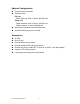
1. Introduction Thank you for purchasing the AMT Datasouth M5 PLUS series Thermal Transfer and Direct Thermal Bar Code Printers. Although the printer takes only a small amount of space, it delivers reliable, superior performance. This printer provides both thermal transfer and direct thermal printing at user selectable speeds of: 2.0, 3.0, 4.0 or 5.0 inches per second (ips), for 203dots per inch (dpi) resolution. And 2.0 or 3.0 ips for 300dpi resolution.
Optional Configurations Peel off module assembly. Guillotine cutter Full cut: Paper thickness: 0.06~ 0.19mm, 500,000 cuts Partial cut: Paper thickness: 0.06~0.12mm, 500,000 cuts Paper thickness: 0.19mm 200,000 cuts Main board integrated with internal Ethernet Internal Ethernet print server module Accessories KP-200 KU-007 plus External Ethernet print server External wireless (802.11b/g) print server External roll mount, media OD. 214 mm (8.
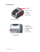
2.3 Printer Parts Clear Window Ribbon Access Cover LED Indicator Feed Button Printer Top Cover Top Cover Open Lever Fig. 1 Top front view 1. USB Interface 2. Centronics Interface 3. RS-232C DB-9 Interface 4. Power Jack 5. Power Switch 6 6. 2 1 3 4 5 Fig.
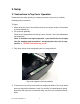
3. Setup 3.1 Instructions to Top Cover Operation Please take care when opening or closing the printer’s top cover by carefully following these instructions. To Open: 1. When facing the front of the printer pull the cover release levers on both sides of printer towards you. 2. Lift up the top gradually. There are two stop positions for the top cover. Position 1 and 2 are indicated on the label below.
Note: DO NOT place your hands or fingers between the top and lower cover while closing! Top cover is fully open and ready to close Use both hands to close the top cover 5. Do not force the cover! If you are not sure if the top cover is fixed at the stop position, please do not force the cover to close. Doing so may damage the cover and support arm. Please open the top cover to the maximum angle and close again. Use both hands to gently press the cover close.
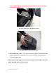
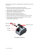
3.2 Setting Up the Printer 1. Place the printer on a flat, secure surface. 2. Make sure the power switch is off. 3. Connect the printer to the computer with the Centronics or USB cable. 4. Plug the power cord into the power supply connector at the rear of the printer, and then plug the power cord into a properly grounded receptacle. Plug USB Power Switch Power Cable Centronics RS-232C Power Supply Fig. 3 Attach power supply to printer 3.
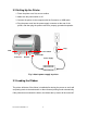
Make sure the printer top cover is engaged properly at both sides prior to powering up the printer. Please follow the steps below to install the ribbon into printer. 1. Push down on the ribbon access window to unlatch and open the cover. 2. Place a paper core onto the ribbon rewind spindle. 3. Mount the ribbon rewind paper core on the front hubs. 4. Install a ribbon on the ribbon supply spindle. 5. Mount the ribbon supply spindle on the rear hubs. 6. Thread the ribbon leader downward pass the print head. 7.
Ribbon supply spindle Ribbon Leader Rear Hub Ribbon Rewind Spindle with Paper Core Fig. 5 Ribbon installation (II) 3.4 Loading Media Stock 1. Insert spindle into a media roll (If your media core is 1 inch, remove the 1.5 inch core adapter from the fixing tab). If label width is 4 inch wide, two fixing tabs are not required). 1.5” Core Paper Roll Adapter* Fixed Tab Printing Side Face Up 1” Media Spindle Fig.
2. Open the printer’s top cover by releasing the green levers located on each side of the printer and lifting the top cover. A top cover support at the rear of the printer will hold the cover open. Lower Cover Fig. 7 Pull the lever to open the cover 3. Place a roll of media onto the internal Media Spindle. 4. Feed the media (printing side face up) under the Teflon bar and through the support guides. The media should come to rest outside the printer. Refer to Fig #8. 5.
Printer Top Cover Top Cover Support Paper Roll Mount Teflon Bar Media Guide Top Cover Open Lever Fig. 8 Media installation (II) 3.5 External Media Roll Mount Installation (Option) 1. Attach an external media roll mount on the bottom of the printer. Fig. 9 Attach the external roll mount to the printer 2. Open the printer top cover by releasing the top cover open levers. The top cover support will hold the cover open. 3. Install a roll of media on the external roll mount. 4.
External Paper Roll Mount External Media Feed Opening Fig. 10 External roll mount media installation (I) 5. Continue feeding the media through the internal printer guides and place it on top of the platen. 6. Adjust the media guides to fit the appropriate width. 7. Close the printer top cover by lifting to the maximum open angle then push down the top cover gently. Rear Media Guide Top Cover Support Arm Media Guide Platen Fig.
3.6 Peel-off Module Installation (Option) 1. Open the top cover and remove the front panel from the printer. Front Panel Fig. 12 Remove the front panel 2. Lift and hold the top cover while pushing down and sliding the cover support arm backwards to release. 3. Use a screwdriver to remove 6 screws on the lower inner cover. Top Cover Top Cover Support Arm Screws Flute Lower Inner Cover Screws Lower Cover Fig.
4. Turn over the printer. Remove two screws located near the top cover hinge, and remove one screw at memory card cover. 5. Separate the top, inner, and the lower cover. 6. Thread the sensor cable through the bezel. Connect the peel-off panel cable to the 5-pin socket on printer PCB. PCB 5-pin Socket Peel-off panel Cable Peel-off panel Mounting Tabs Fig. 14 Connect peel-off sensor cable to main board Bezel Slot Fig.
7. Insert the peel-off assembly tabs into the lower inner cover hinge holes until they snap into place. Lower Inner Cover Roller Lower Cover Peel Off Assembly Tab Inner Hinge Holes Fig. 16 Peel-off panel installation (I) 8. Reassemble parts in reverse procedures after installing the module. Peel-off panel Roller Fig. 17 Peel-off panel installation (II) 9. Lift up the peel-off panel and snap into place to close. 10. Use a screwdriver to secure enclosure cover screws (9-places). 11.
3.6.1 Loading Labels into Peel-off Module Note: Both thermal paper and plain paper labels apply for peel-off function, neither PVC nor vinyl work with peel-off function. 1. Insert a 1” label spindle into a label roll. 2. Open the printer top cover by pulling the top cover open levers. The top cover support will hold the printer top cover. Peel-off panel Backing paper Top Cover Open Lever Opening Fig. 18 Open the top cover 3. Install the label roll onto the paper roll mount. 4.
5. Feed the label, printing side facing up, through the paper guides and place it on top of the platen. 6. Thread the label through the liner opening, which is beneath the roller and tear off one piece of the label. 7. Adjust the paper guides by moving left or right to fit the label/backing width. Top Cover Top Cover Support Roller Peel-off panel Fig. 20 Load label into peeler roller assembly 8. Lift the peel-off panel up and back into the closed position. 9.
3.7 Cutter Module Installation (Option) 1. Pull the top cover open levers to open the top cover. 2. Remove the front panel from the lower cover. Lower Cover Fig. 22 Pull the lever to open the cover 3. Lift and hold the top cover while pushing down and sliding the cover support arm backwards to release. 4. Use a screwdriver to remove 6 screws on the lower inner cover. Top Cover Top Cover Support Screws Flute Front Panel Lower Inner Cover Lower Cover Screws Fig.
5. Turn over the printer. Remove two screws located near the top cover hinge. 6. Remove the screw from the memory card cover, and left the cover off. Plug in the cutter driver IC at U14 (M5) / U30 (M5 PLUS) socket on the main board. 7. Use both thumbs to hold the lower cover and index fingers to lift up the top cover open levers to separate the lower inner cover and the lower cover. 8. Thread the cable through the bezel. Connect the cutter module cable to the 4-pin socket on printer PCB.
9. Assemble the lower inner cover back onto the lower cover. 10. Install the cutter into the slots of the printer inner cover. Cutter Slot Fig. 26 Cutter module installation 11. Use a screwdriver to secure enclosure cover screws (9-places). 12. Close the top cover by placing the top cover support arm back into the flute and push it forward, then close the top cover slowly. 3.7.1 Loading Media in Cutter Mode 1. 2. 3. 4. Insert media spindle into a roll. Open the printer top.
Top Cover Top Cover Support Arm Paper Guide Platen Cutter Fig. 27 Media installation in cutter mode 7. Close the top cover by lifting upward to the maximum open position, then close slowly. Fig.
3.8 Diagnostic Tool The Diagnostic Utility is a toolbox that allows users to explore the printer's settings and status; change printer settings; download graphics, fonts, and firmware; create printer bitmap fonts; and to send additional commands to the printer. Using this convenient tool, you can explore the printer status and settings and troubleshoot the printer. Note: This utility works with printer firmware V6.00 and later versions. 3.8.1 Start the Diagnostic Tool 1.
3.8.2 Printer Function (Calibrate, Ethernet, RTC setup…) 1. Select the PC interface connected with bar code printer. 2. Click the “Function” button to setting. 3. The detail functions in the Printer Function Group are listed as below. Function Description Factory Default Initialize the printer and restore the settings to factory default. Dump Text To activate the printer dump mode. Configuration Page Print printer configuration. Synchronize printer Real Time Clock with RTC Setup PC.
3.9 Install Memory Card 1. Turn the printer upside down. 2. Remove the screw that fixes the memory card cover. Screw Memory Card Cover 3. Plug in the memory card on main board. M5 Model (Option) 4. M5 PLUS Model (SD Card) Close the memory card cover. * Recommended SD card specification. SD V 1.0, V 1.1 128MB SD V 2.0 (SDHC) 4GB class 6 256MB 512MB 1GB -Supported DOS FAT file system. -Folders stored on the SD card should be in the 8.3 filename format.
4. Power on Utilities There are six power-on utilities to set up and test printer hardware. These utilities are activated by pressing FEED button and by turning on the printer power simultaneously. The utilities are listed as below: 1. Ribbon sensor calibration and Gap or black mark sensor calibration 2. Gap/black mark sensor calibration, Self-test and dump mode 3. Printer initialization 4. Set black mark sensor as media sensor and calibrate the black mark sensor 5.
4.2 Gap/Black Mark Calibration, Self-test and Dump Mode While calibrate the gap/black mark sensor, printer will measure the label length, print the internal configuration (self-test) on label and then enter the dump mode. To calibrate gap or black mark sensor, depends on the sensor setting in the last print job. Please follow the steps below to calibrate the sensor. 1.Turn off the power switch. 2. Hold on the button then turn on the power switch. 3. Release the button when LED becomes amber and blinking.
Self-test Printer will print the printer configuration after gap/black mark sensor calibration. Self-test printout can be used to check if there is any dot damage on the heater element, printer configurations and available memory space.
Dump mode The printer will enter dump mode after printing the printer configuration. In the dump mode, all characters will be printed in 2 columns as following. The left side characters are received from your system and right side data are the corresponding hexadecimal value of the characters. It allows users or engineers to verify and debug the program. ASCII Data Hex decimal data related to left column of ASCII data Fig.
4.3 Printer Initialization Printer initialization is used to clear DRAM and restore printer settings to defaults. The only one exception is ribbon sensitivity, which will note be restored to default. Printer initialization is activated by the following procedures. 1. Turn off the power switch. 2. Hold on the button then turn on the power switch. 3. Release the button when LED turns green after 5 amber blinks. (Any green will do during the 5 blinks).
4.4 Black Mark Sensor Setting and Calibration Please follow the steps as below. 1. Turn off the power switch. 2. Hold on the button then turn on the power switch. 3. Release the button when LED turns green/amber after 5 green blinks. (Any green/amber will do during the 5 blinks). The LED color will be changed as following: Amber red (5 blinks) amber (5 blinks) green (5 blinks) green/amber (5 blinks) red/amber (5 blinks) solid green 4.5 Gap Sensor Setting and Calibration Please follow the steps as below.
3. Release the FEED button when LED becomes solid green. The LED color will be changed in the following: Amber red (5 blinks) amber (5 blinks) green (5 blinks) green/amber (5 blinks) red/amber (5 blinks) solid green 4. Printer will be interrupted to run the PAL application program. 5. Maintenance 5.1 Cleaning This session presents the cleaning tools and methods to maintain your printer. 1. Please use one of following material to clean the printer.
ethanol and a cotton swab, or lint-free cloth. Tear Bar/Peel Use the lint-free cloth with 100% As needed ethanol to wipe it. Bar Sensor Compressed air or vacuum Monthly Exterior Wipe it with water-dampened cloth As needed Interior Brush or vacuum As needed Note: Do not touch print head by hand. Should it be touch accidentally, please use ethanol to clean it. Please use 100% Ethanol. DO NOT use medical alcohol, which may damage the printer head.
and from the power supply to the printer power jack if they are connected securely. Solid Green ON The printer is ready * No action necessary. to use Green with Pause blinking Red with Error blinking The printer is * Press the FEED button to resume for paused printing. The out of label or 1. Out of label or ribbon ribbon or the * Load a roll of label and follow the printer setting is instructions in loading the media then not correct press the FEED button to resume for printing.
The Ethernet IP, subnet mask, gateway is not configured properly. No print on the label Continuous feeding labels Configure the IP, subnet mask and gateway. Label or ribbon loaded not Follow the instructions in loading correctly. the media or loading the ribbon. Ribbon run out. Loading the ribbon. The printer setting may go wrong. Please do the initialization and gap/black mark calibration. Gap/black mark sensor sensitivity Calibrate the gap/black mark sensor.
7. LED and Button Operation 7.1 LED LED Color Description Green/ Solid This illuminates that the power is on and the device is ready to use. Green/ Flash This illuminates that the system is downloading data from PC to memory and the printer is paused. Amber This illuminates that the system is clearing data from printer. Red / Solid This illuminates printer head open, cutter error.
Ribbon Sensor and 1. Turn off the power switch. Gap/Black Mark 2. Hold on the button then turn on the power switch. Sensor Calibration 3 Release the button when LED becomes red and blinking. (Any red will do during the 5 blinks). It will calibrate the ribbon sensor and gap/black mark sensor sensitivity.
Printer Initialization 1. Turn off the power switch. 2. Hold on the button then turn on the power switch. 3. Release the button when LED turns green after 5 amber blinks. (Any green will do during the 5 blinks). The LED color will be changed as following: Amber red (5 blinks) amber (5 blinks) (5 blinks) green/amber (5 blinks) blinks) solid green green red/amber (5 Note: Always do gap/black mark sensor calibration after printer initialization. Set Black Mark 1. Turn off the power switch.
Skip AUTO.BAS 1. Turn off printer power. 2. Press the FEED button and then turn on power. 3. Release the FEED button when LED becomes solid green. The LED color will be changed as following: Amber red (5 blinks) amber (5 blinks) green (5 blinks) green/amber (5 blinks) red/amber (5 blinks) solid green 4. Printer will be interrupted to run the AUTO.BAS program.
Revise History Date 9-19-08 Content Pre-Production Release Document #120522 Rev-A 38 Editor J.
Document #120522 Rev-A Corporate Headquarters Manufacturing/Service 803 Camarillo Springs Road, Suite-D Camarillo, CA 93012 TEL: 800.215.9192 FAX: 805.484.5282 Web site: www.AMTDatasouth.com 5033 Sirona Drive, Suite-800 Charlotte, NC 28273 TEL: 800.476.2120 FAX: 704.525.