Logic MMC Installation Manual 527-327 Issue 5 © 2002 AMS Neve plc own the copyright of all information and drawings contained in this manual which are not to be copied or reproduced by any means or disclosed in part or whole to any third party without written permission. HEAD OFFICE As part of our policy of continual product improvement, we reserve the right to alter specifications without notice but with due regard to all current legislation.
Logic MMC Installation Manual CONTENTS INSTALLING LOGIC MMC 1 Important note for customer attention 1 Initial Checks 1 Optional Equipment 1 Static Sensitive Devices Handling Precautions 2 Cable Lengths 3 Rack-Mounting 4 Cooling 4 Technical Earth 4 Safety Earth 4 Mains Power 5 Power Requirements 5 Console Data 5 Rack Data 5 Connecting the System 6 VARICON TABLES AND CUSTOM INTERCONNECTS 7 CONNECTOR DETAILS 8 Console Connections 8 SPS Rack 10 Encore Processor Rack 17 M
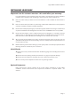
Logic MMC Installation Manual INSTALLING LOGIC MMC Important note for customer attention - this could affect your warranty: It is important that you refer to this document. Information is provided concerning the installation procedure from unpacking and assembling to powering up the system ready for use. - Failure to follow these procedures and recommendations could invalidate the manufacturer’s warranty.
Logic MMC Installation Manual Static Sensitive Devices Handling Precautions Introduction This Specification details the precautions to be used for the Protection of Semi-Conductor Devices. Static Charge build up in humans, tools, fixtures etc., could appear as a voltage difference applied between the leads of a device, leaving either immediate or latent damage. Component and Package Identification from AMS Neve plc Containers and Packages holding Semi-Conductive Devices will be suitably marked.
Logic MMC Installation Manual Cable Lengths The maximum length of the digital communication cable (Tranlink) between the console and the racks which can be guaranteed to work is 30 metres. However, lengths of up to 50 metres have worked successfully but care must be taken to avoid sharp kinks in the cable and runs in the proximity of interfering signals. The standard length supplied is 10 metres. Any other length should be specified at the time of ordering.
Logic MMC Installation Manual Rack-Mounting The rack units should be installed in a 19" cabinet with access to the front and rear. A rack depth of 700mm minimum is required for clearance of cabling and connectors. Ventilation panels must be provided to allow a free flow of air both across the rack and from the front to the back. It is recommended that chassis support rails are used to provide rear support to all units over 3U.
Logic MMC Installation Manual Mains Power The console is DC powered and requires a bulk PSU to be fitted in a machine room. This unit holds two hot-swap modules each of which has an independant mains feed which gives full redundancy. Typical power consumption given below is based on fully populated racks. Check that the voltage selector on the rear of the Encore Processor Rack, Relay Control Unit and Remote 8 Channel Level Control Unit is set to the correct operating voltage.
Logic MMC Installation Manual Connecting the System When the units are in position and all the cables have been identified and prepared, connect the system as shown in the Custom Interconnect section. Console to Racks Audio Interconnect The Audio Cable from the Console is supplied with cable ends stripped and tinned only ready for custom installation requirements.
Logic MMC Installation Manual VARICON TABLES AND CUSTOM INTERCONNECTS Varicon tables and custom interconnects are shown on the following pages: Issue 5 Page 7
AUXILIARY Issue 5 TRANLINK AUTOMATION VGA I/P KEYBOARD SECONDARY VGA I/P MOUSE EDITOR VGA I/P REMOTE CNTRL O/P AUDIO IN RIGHT MAIN LS O/P LEFT RIGHT SMALL LS1 O/P LEFT RIGHT SMALL LS2 O/P LEFT RIGHT STUDIO OUT LEFT RIGHT H/PHONE LINE O/P LEFT H/POHONES Logic MMC Installation Manual CONNECTOR DETAILS Console Connections Page 8
Logic MMC Installation Manual Audio Input Cable Wiring Location: Mating Connector: Rear of Console 25-way D type male Cabling Information: Use high quality screened twisted-pair cable Pin No.
Logic MMC Installation Manual SPS Rack VIDEO A VIDEO B VITC WCK IN WCK OUT TIMECODE IN TACH IN AES SYNC IN MC#1 MC#2 MC#3 IN MADI 5 OUT SERVICES IN MADI 6 OUT TIMECODE OUT TACH OUT MIC/LINE IN MADI 7 OUT MC#4 MC#5 MC#6 IN MADI 8 OUT A TRANLINKS B C D IN MADI 1 OUT IN MADI 2 OUT IN MADI 3 OUT IN MADI 4 OUT E PSU 2 Issue 5 PSU 1 Page 10
Logic MMC Installation Manual MACHINE CONTROL PORTS #1,#2,#3,#4 and #5 Location: Mating connector: Cabling Information: Rear of SPS Rack DE 9P Use a twisted pair screened cable with EMC hoods. Twisted pairs should be used with Rx–, Rx+ and Tx–, Tx+ as twisted pairs. The cable screen should be 360º terminated to an EMC backshell at each end. Pin No.
Logic MMC Installation Manual MACHINE CONTROL PORTS #1,#2,#3,#4 and #5 Serial RS422 Device e.g. Sony 9-pin (P2 Protocol) Location: Cabling Information: Rear of SPS Rack Use high quality screened twisted–pair cable, paying careful attention to correct pairing. Screens should be 360º terminated to EMC backshells at both ends. Length as required – recommended maximum 50m.
Logic MMC Installation Manual MACHINE CONTROL PORT #2 & #4 ES1–11 Cable (also ES1–12, ES/2, Synchronet) Location: Cabling Information: Rear of SPS Rack Use high quality screened twisted–pair cable, paying careful attention to correct pairing. A screened twisted-pair cable should also be used for the XLR connection with the screens connected to both ends. Screens should be 360º terminated to EMC backshells at both ends. Length as required – recommended maximum 50m.
Logic MMC Installation Manual MACHINE CONTROL PORT #6 Location: Mating connector: Cabling Information: Rear of SPS Rack DA 15 P A screened twisted-pair cable should be used with the screens 360º terminated to EMC backshells at both ends. Signal pairs 1 & 2, 3 & 4, 5 & 6, 9 & 10 and 14 & 15 should all use twisted pairs of the same cable. Logic MMC Pin No. Signal Sony 9-Pin Pin No.
Logic MMC Installation Manual MACHINE CONTROL PORT #6 Location: Mating connector: Rear of SPS Rack DA 15 P Logic MMC Pin No. Standard ES Bus Cable Signal ES1–11, ES1– 12, ES/2, Synchronet Pin No.
Logic MMC Installation Manual SERVICES PORT Location: Mating connector: Cabling Information: Rear of SPS Rack DB 25 P A screened twisted-pair cable should be used with the screens 360º terminated to EMC backshells at both ends. If this port is taken to more than one destination then all cable screens must still be terminated to EMC backshells. Pin No.
Logic MMC Installation Manual Encore Processor Rack MAINS VOLTAGE: FREQUENCY: CURRENT: FUSE RATING: MON SCSI MODEM NET 1 DSP/ SOUND SAM COMMS 1 1 2 3 AUXILIARY 4 1 2 TRANLINK AMS NEVE ENCORE FOR DFC/LIBRA 2 230 Issue 5 Page 17
Logic MMC Installation Manual MIOS Rack MON O/Ps 3 2 1 4 TECH EARTH IN AES SYNC OUT IN WCLK OUT PSU2 LINE OUT E - MIC C MIC B MIC A COAXIAL MADI CTRL IN GP INPUTS CTRL OUT GP OUTPUTS COMMS PSU1 LINE IN D RX2 TX2 RX1 TX1 90V - 240V AC 1.5A MAX 50HZ-60HZ T 3.2A H 250V AES I/O F WARNING DISCONNECT MAINS LEAD TO ISOLATE UNIT. NO USER SERVICEABLE PARTS INSIDE. HAZARDOUS VOLTAGES INSIDE. REFER TO MANUALS AMS NEVE model type serial no. made in U.K.
24 120 0 Issue 5 OPTO INPUT 1-16 EXT 113-128 RELAY 49-64 EXT 97-112 RELAY 33-48 EXT 81-96 RELAY 17-32 RELAY 1-16 EXT 65-80 Logic MMC Installation Manual Relay Control Unit (Fader Start) Page 19 TRANLINK B TRANLINK A
Logic MMC Installation Manual RELAY CONNECTORS Location: Rear of Relay Contol Unit Mating connector required: 37–way D type male PINOUT : 37 WAY RELAY LOOP D’S MAX CURRENT THROUGH EACH PAIR : 0.
Logic MMC Installation Manual OPTO–ISOLATED READER INPUTS Location: Rear of Relay Control Unit Mating connector required: 37–way D type male OPTO–ISOLATED READER INPUTS : ‘OPTO INPUT 1–16’ Notes : +5v MUST be connected via 470 ohm resistor to limit current into opto inputs to 10mA. Rec Tally MUST be connected via a series 2.7k ohm resistor to limit current into opto inputs. Record & Play Tallies for Multitrack shown below are Active Low.
Logic MMC Installation Manual 24 120 0 REMOTE CONTROL 7 8 6 4 5 OUTPUTS 3 1 2 7 8 6 5 INPUTS 4 3 1 2 Remote 8 Channel Level Control Unit Issue 5 Page 22
Issue 5 PSU 1 PSU 2 0.7A/0.45A T 1.6A H 250V 110V - 230V AC 50HZ - 60HZ 0.7A/0.45A T 1.
Logic MMC Installation Manual AES-EBU IN - Standard I/O Location: Rear of Multichannel AES I/O Unit Mating connector required: 37-way D type male Issue 5 Pin No.
Logic MMC Installation Manual AES-EBU OUT - Standard I/O Location: Rear of Multichannel AES I/O Unit Mating connector required: 37-way D type male Issue 5 Pin No.
Logic MMC Installation Manual AUX AES-EBU IN - Optional Expansion 1 or 2 Cards Location: Rear of Multichannel AES I/O Unit Mating connector required: 50-way D type male Issue 5 Pin No.
Logic MMC Installation Manual AUX AES-EBU OUT - Optional Expansion 3 or 4 Cards Location: Rear of Multichannel AES I/O Unit Mating connector required: 50-way D type male Issue 5 Pin No.