SUM100 LINE/SUM/LINE AMPLIFIER OPERATING AND MAINTENANCE MANUAL © Copyright 1997-2005, Audio Technologies Incorporated - Printed in USA Audio Technologies Inc. | 154 Cooper Road #902 | West Berlin, NJ 08091 | Voice 856-719-9900 | Fax 856-719-9903 | www. audio.
DESCRIPTION The SUM100 Summing Amplifier is an inexpensive, high performance amplifier that is designed as a line level stereo to mono summing amplifier. It is also useful as a gain block, and as an impedance converter and summing for IHF (RCA type) signals. The inputs provide balanced 40Kohm bridging impedance for line levels up to +24dBm. The high input impedance allows the SUM100 inputs to also bridge 10dBu (hi-fi, RCA plug) lines without loading.
GAIN STAGE A low noise NE5532 section (A1A) provides 26dB maximum gain. A linear control is used in a unique circuit configuration to provide a wide range logarithmic MASTER gain control characteristic in a variable gain stage with optimum noise performance. Output noise at unity gain is low enough to allow performance to exceed 16-bit digital dynamic range even at -10dBu nominal output. Unity overall gain is achieved at approximately 12 o’clock pot position.
company inspect the unit and the box at your location. Count the pieces! Don't throw out the boxes and packing material until you are sure you have everything that is coming to you. The amplifiers need either their own separately ordered WA100 power supply or a DC cable, P/N20602-1 to share the supply of another amplifier. Rack and desk mounting hardware may be packed in with the unit even though ordered separately.
shielded and free of ground loops. It may even be necessary to add shielding to the DC input leads to avoid RF pickup. POWER DISTRIBUTION Multiple amplifiers sharing a single wall-wart power supply should be looped through each other using the DC interconnect cables P/N20602-1.
36VDC will cause some increased internal heating, but above 36VDC may cause IC failure. OPERATING POINTS An internal reference voltage equal to 1/2 the supply voltage is generated. All audio stage IC inputs and outputs should show a DC level equal to this voltage when measured with a high impedance meter. Audio inputs and outputs are capacitor coupled and ground referenced. MODIFICATIONS ADDITIONAL GAIN If more gain is required for a particular application increase the values of R25 (left) and R34 (right).
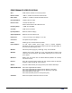
PERFORMANCE SPECIFICATIONS Gain: 28dB maximum, 0dB at 12 o’clock pot position Nominal Levels: +4dBu in, +4dBm out to 600 ohm balanced load Peak Levels: +24dBu in, +22 dBm out to 600 ohm balanced load Noise 20kHz B.W.: -90dBm maximum output Harmonic Dist.: .02% Max at Peak Level 20Hz to 20 kHz .005% max at Nominal Level Frequency Resp.: +.