AT602 AND AT1202 2-CHANNEL POWER AMPLIFIER OWNER’S GUIDE TRANSLATING TECHNOLOGY
Please Read First Safety Instructions WARNING: TO REDUCE THE RISK OF FIRE OR ELECTRIC SHOCK, DO NOT EXPOSE THIS UNIT TO RAIN OR MOISTURE. Read all the safety and operating instructions before connecting or using this unit. CAUTION: To reduce the risk of electrical shock, do not remove the cover (or back). No user serviceable parts inside. Refer servicing to qualified service personnel. WARNING: To reduce the risk of fire or electric shock, do not expose this appliance to rain or moisture.
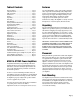
Table of Contents Features Please Read First ............................................................ Page 2 Safety Instructions ........................................................ Page 2 Table of Contents .......................................................... Page 3 Introduction ................................................................... Page 3 Features ........................................................................... Page 3 Unpacking .......................................
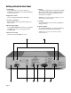
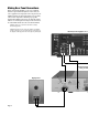
Getting to Know the Rear Panel A Audio Inputs Use the INPUT jacks to connect to the outputs of a preamplifier, receiver with preout connections, CD player, or other control devices. F AC Fuse Your amplifier is supplied with a rear panel mounted main AC fuse. This main fuse may need replacement if the unit will not turn on. Never replace the the main fuse with other than the one indicated. B Input Gain Controls Use these to adjust the input gain of each channel.
Connecting Your Amplifier When making connections between any source components and the amplifier, or when making connections to any speaker, be certain that both the input devices and the amplifier are turned off. To assure that there will be no unwanted signal transients that can damage equipment or speakers, it is always best to unplug all equipment before making any connections. Input Connections Connecting the amplifier to your source equipment is simple.
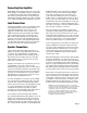
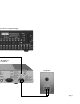
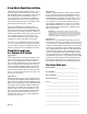
Making Rear Panel Connections When connecting the amplifier to your source equipment, match the output channel designations on the rear of your source equipment to the input jacks on the rear panel of your amplifier that have the same channel name. Correct polarity connections are important to maintain proper speaker phasing. When making connections to the amp and speakers, adhere to a consistent pattern of using one side of the wire to the red terminals and the other side to the black terminals.
essor Shown as a Typical Example e, The Amplier Is or a 2nd Zone Left Speaker Page 7
Power Control Connections Amplifier Operation Your amplifier features a built-in remote turn-on system that will automatically switch the amplifier on when another device in the system is switched on. After all connections have been made you are ready for operation. First, turn on the source component in your system. It is always a good idea to turn on your amplifier LAST.
AC Fuse ATI Service Information Your amplifier is supplied with a rear panel mounted main AC fuse. This main fuse may need replacement if the unit will not turn on. Never replace the the main fuse with other than the one indicated. The AT602 and the AT1202 do not contain any user serviceable parts inside. If you suspect a problem that may require service assistance, contact us at amptech@ix.netcom.com, or by phone at 888-777-8507.
A Few Words About Hum and Noise Audible hum, or a discernable low frequency noise, is one of the most common problems in audio/video systems. This hum, which may be present even when the volume is at a low level, is usually caused by a problem known as “ground loops”. A ground loop occurs when there is a difference in ground voltages between two or more components that are connected electrically. This, in turn, creates multiple current paths and causes the low-level noise, or hum.
Power Amplifier Specifications The following applies to all channels being driven simultaneously with 8 ohm loads and an input sensitivity of 28dB gain unless otherwise specified. Series AT602 AT1202 2 2 EIA 1kHz Output Power at 8 Ohms* 75 watts 140 watts EIA 1kHz Output Power at 4 Ohms* 110 watts 220 watts FTC Full Bandwidth Output Power at 8 Ohms** 60 watts 120 watts FTC Full Bandwidth Output Power at 4 Ohms** 90 watts 180 watts Input Sensitivity for Full Rated Power 0.9 Volts 1.
90-Day Limited Warranty Terms and Conditions (7-Year Optional Extended Warranty) This ATI product is warranted against defects in materials and workmanship for 90 days from the date of purchase by the original owner. The date of purchase shall be established by the original owner presenting to the ATI Customer Service Facility the original owner’s purchase receipt or sales slip showing from whom the product was purchased, the date of purchase and the purchase price of the unit.