
Instruction manual


AMPDIO DRIVERS
Page 132
TCfreeResource
6.4.8.2 Generate Astable Multivibrator Waveform — TCsetAstable
Generates a clock signal of specified frequency and mark-to-space ratio. This is implemented
on two counters, both in mode 1 (digital one-shot). One counter counts the mark time and the
other counts the space time. The outputs of each counter/timer control the gate of the other,
so that when the mark times-out, the space counter is triggered and vice versa. N.B. the user
must connect each counter’s gate to the other’s output on the user connector SK1. See
section 3.1.3 for more details on the Astable application.
For cards without a Counter Connections Register block (e.g. PC214E) an input clock
frequency of 1 MHz is assumed (4 MHz is assumed for PC27E).
For cards with a Counter Connections Register block, the highest internal clock frequency in 1
kHz, 10 kHz, 100 kHz, 1 MHz or 10 MHz that will support the required mark or space duration
is used and chosen individually for each counter.
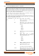
i = TCsetAstable (h, chip, chan, chipS, chanS, freq, msratio)
where h short: board handle as issued by the
registerBoardEx function.
chip short: address offset of timer/counter chip.
One of the following pre-defined constants may
be used:
X1 = 0
X2 = 4
Y1 = 8
Y2 = 12
Z1 = 16
Z2 = 20
chan short: timer/counter channel number within the
chip (0, 1 or 2).
chipS short: address offset of secondary
timer/counter chip. One of the following pre-
defined constants may be used:
X1 = 0
X2 = 4
Y1 = 8
Y2 = 12
Z1 = 16
Z2 = 20
chanS short: secondary timer/counter channel
number within the chip (0, 1 or 2).
freq float: desired frequency, in Hertz.
The frequency must be at least 0.005 Hz.
msratio float: desired mark-to-space ratio, defined as
(mark time/period), i.e. 0 is D.C. 0V, 1 is D.C.
5V, 0.5 is symmetrical square wave, i.e. high