
Instruction manual


PC27E Page 17
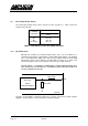
7. Frequency Counter
8. EXIT to DOS
6.3 Copyright
The software on the demonstration disk is copyright Amplicon Liveline Ltd. Any user who has
purchased a PC27E may use the software, or any part of it, for use in his own programs, or
for resale when delivered with a PC27E.
6.4 Programming the 82C53 Counter/Timers
The three counter/timers of the 82C53 can be independently programmed to operate in any
one of six modes. These are:
1. Mode 0: Interrupt on Terminal Count.
2. Mode 1: Programmable One Shot.
3. Mode 2: Rate Generator.
4. Mode 3: Square Rate Generator.
5. Mode 4: Software Triggered Strobe.
6. Mode 5: Hardware Triggered Strobe.
Details of the operation of these various modes are contained in Appendix 82C53.
The function of a particular timer/counter is established by writing a control word to the control
register. This 8 bit word consists of four fields as follows:
D7 D6 D5 D4 D3 D2 D1 D0
Select Read/ Load Select Mode BCD or
Counter Binary
D0 = 0: binary selected.
= 1: BCD selected.
D3,D2,D1 = 0 0 0: Mode 0 selected.
= 0 0 1: Mode 1 selected.
= 1 0 1: Mode 5 selected.
D5,D4 = 0 0: Latch Counter.
= 0 1: Read/Load of LSB only
= 1 0: Read/Load of MSB only
= 1 1: LSB followed by MSB
D7,D8 = 0 0: Counter 0 selected.
= 0 1: Counter 1 selected.
= 1 0: Counter 2 selected.
= 1 1: Prohibited combination.