
Instruction manual

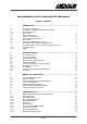
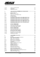
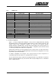
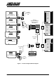
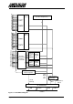
Table Of Contents
- INTRODUCTION
- GETTING STARTED
- MAKING THE CONNECTIONS
- USING THE PC215E
- STRUCTURE AND ASSIGNMENTS OF THE REGISTERS
- Register Assignments
- Register Groups
- The Register Details
- Programmable Peripheral Interface PPI-X Data Register Port A
- Programmable Peripheral Interface PPI-X Data Register Port B
- Programmable Peripheral Interface PPI-X Data Register Port C
- Programmable Peripheral Interface PPI-X Command Register
- Programmable Peripheral Interface PPI-Y Data Register Port A
- Programmable Peripheral Interface PPI-Y Data Register Port B
- Programmable Peripheral Interface PPI-Y Data Register Port C
- Programmable Peripheral Interface PPI-Y Command Register
- Z1 Counter 0 Data Register
- Z1 Counter 1 Data Register
- Z1 Counter 2 Data Register
- Counter/Timer Z1 Control Register
- Z1 Counter/Timer Status Register
- Z2 Counter 0 Data Register
- Z2 Counter 1 Data Register
- Z2 Counter 2 Data Register
- Counter/Timer Z2 Control Register
- Z2 Counter/Timer Status Register
- Group Z Clock Connection Register
- Group Z Gate Connection Register
- Interrupt Source Selection Register
- Interrupt Status Register
- PROGRAMMING THE PC215E
- Copyright
- Files installed from the Distribution Diskette
- Windows DLL and Examples
- DOS 'C' Library and Examples
- Using the Dynamic Link Library
- Windows and DOS Library Functions
- Initialisation Functions
- Interrupt Control Functions
- Data Buffer Functions
- Timer/Counter Functions
- Differential Counter Functions
- Frequency Generation Functions
- Millisecond Stopwatch Functions
- Frequency Input and Output Functions
- Digitally- and Voltage-Controlled Oscillator Functions
- Digital Input/Output Functions
- Switch Scanner Matrix Functions
- Bi-Directional Data Bus Functions
- PC215E Library Error Codes
- PC215E Interface Guide For LABTECH NOTEBOOK
- Guide to User Programming
- Signal Centre
- CONTENTS
- DECLARATION OF CONFORMITY

PC215E Page 4
1.4 Features of the PC215E
• Six 16-bit, 10 MHz counter/timers, each with six programmable counter modes
• Crystal clock/divider with 5 rates, independently software-selectable for each counter/timer
clock input
• Independent software-selectable clock and gate inputs for each counter/timer
• 48 programmable digital I/O lines, with three operating modes
• Six software-selectable interrupt sources - two timer output and four digital I/O
1.5 PC215E General Description
The PC215E is a half-size ISA bus plug-in board which provides 48 programmable digital
input/output lines, and six independent programmable 16 bit counter/timers. The board can be
installed in IBM
©
or fully compatible PC/AT computers.
The flexible addressing system provided on the board allows the base address to be set within
the range 000 to FF0
16
. The board interrupt level can be software selected to IRQ3, IRQ5,
IRQ7, IRQ9, IRQ10, IRQ11, IRQ12 or IRQ15, and any number of five possible interrupt sources
can be software selected.
A 10 MHz on-board crystal oscillator provides an accurate, stable clock source for the
counter/timers, independent of the system clock frequency. A divider circuit provides five
selectable frequencies (10 MHz, 1 MHz, 100 kHz, 10 kHz and 1 kHz) derived from the oscillator,
and each of the counter/timer clock inputs can be automatically connected to any of these clock
sources, or to its own individual external clock source, or to the output of another counter/timer.
Each of the counter/timer gate inputs can be enabled and disabled in software, or automatically
connected to its own external gate source, or the output of another counter/timer.
A block diagram of the PC215E is given in Figure 2.
1.5.1 The Software
The PC215E is supplied with a 3½” diskette containing the software, which supports all
five of the boards in the 200 Series Digital I/O Counter/Timer Family. This software is
described fully in section 6 of this manual.
1.5.1.1 Windows Installation Program
The software is installed onto the user's hard disk by a Windows installation program.
See section 2 of this manual for information on getting started.
1.5.1.2 Windows DLL
A Windows Dynamic Link Library (DLL) containing over 50 functions provides an
Applications Program Interface (API) to the PC215E, and the other boards in the family.
The library functions allow the boards to be easily applied to many different applications,
and also provide an easy way of accessing the board's features. The 16-bit DLL can be
called by any language which uses Windows calling conventions, and example programs
written in Microsoft Visual Basic are also provided.