
Instruction manual

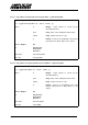


Table Of Contents
- INTRODUCTION
- GETTING STARTED
- MAKING THE CONNECTIONS
- USING THE PC215E
- STRUCTURE AND ASSIGNMENTS OF THE REGISTERS
- Register Assignments
- Register Groups
- The Register Details
- Programmable Peripheral Interface PPI-X Data Register Port A
- Programmable Peripheral Interface PPI-X Data Register Port B
- Programmable Peripheral Interface PPI-X Data Register Port C
- Programmable Peripheral Interface PPI-X Command Register
- Programmable Peripheral Interface PPI-Y Data Register Port A
- Programmable Peripheral Interface PPI-Y Data Register Port B
- Programmable Peripheral Interface PPI-Y Data Register Port C
- Programmable Peripheral Interface PPI-Y Command Register
- Z1 Counter 0 Data Register
- Z1 Counter 1 Data Register
- Z1 Counter 2 Data Register
- Counter/Timer Z1 Control Register
- Z1 Counter/Timer Status Register
- Z2 Counter 0 Data Register
- Z2 Counter 1 Data Register
- Z2 Counter 2 Data Register
- Counter/Timer Z2 Control Register
- Z2 Counter/Timer Status Register
- Group Z Clock Connection Register
- Group Z Gate Connection Register
- Interrupt Source Selection Register
- Interrupt Status Register
- PROGRAMMING THE PC215E
- Copyright
- Files installed from the Distribution Diskette
- Windows DLL and Examples
- DOS 'C' Library and Examples
- Using the Dynamic Link Library
- Windows and DOS Library Functions
- Initialisation Functions
- Interrupt Control Functions
- Data Buffer Functions
- Timer/Counter Functions
- Differential Counter Functions
- Frequency Generation Functions
- Millisecond Stopwatch Functions
- Frequency Input and Output Functions
- Digitally- and Voltage-Controlled Oscillator Functions
- Digital Input/Output Functions
- Switch Scanner Matrix Functions
- Bi-Directional Data Bus Functions
- PC215E Library Error Codes
- PC215E Interface Guide For LABTECH NOTEBOOK
- Guide to User Programming
- Signal Centre
- CONTENTS
- DECLARATION OF CONFORMITY

Page
71
PC215E
6.6.4.3 Connect Timer/Counter Clock Source - TCsetClock
Configures a timer/counter clock input source.
i = TCsetClock(h, chip, chan, clk)
where
h Integer. Board handle as issued by the
registerBoard function.
chip Integer. Address offset of the timer/counter
chip. One of the following pre-defined constants
may be used:
X1 = 0
X2 = 4
Y1 = 8
Y2 = 12
Z1 = 16
Z2 = 20
chan Integer. Timer/counter channel number within
the chip (0, 1 or 2).
clk Integer. Clock source. Use one of the following
pre-defines constants representing the valid
clock sources:
CLK_CLK = 0: external CLK(chan) i/p
CLK_10MHZ = 1: internal 10 MHz
CLK_1MHZ = 2: internal 1 MHz
CLK_100KHZ = 3: internal 100 kHz
CLK_10KHZ = 4: internal 10 kHz
CLK_1KHZ = 5: internal 1 kHz
CLK_OUTN_1 = 6: OUT (chan-1)
CLK_EXT = 7: external EXTCLK (chip) i/p
Returns Integer:
OK
or ERRHANDLE
ERRCHAN
ERRDATA
Prior Calls registerBoard
See Also TCsetGate