
Instruction manual


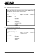

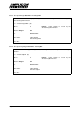

Table Of Contents
- INTRODUCTION
- GETTING STARTED
- MAKING THE CONNECTIONS
- USING THE PC215E
- STRUCTURE AND ASSIGNMENTS OF THE REGISTERS
- Register Assignments
- Register Groups
- The Register Details
- Programmable Peripheral Interface PPI-X Data Register Port A
- Programmable Peripheral Interface PPI-X Data Register Port B
- Programmable Peripheral Interface PPI-X Data Register Port C
- Programmable Peripheral Interface PPI-X Command Register
- Programmable Peripheral Interface PPI-Y Data Register Port A
- Programmable Peripheral Interface PPI-Y Data Register Port B
- Programmable Peripheral Interface PPI-Y Data Register Port C
- Programmable Peripheral Interface PPI-Y Command Register
- Z1 Counter 0 Data Register
- Z1 Counter 1 Data Register
- Z1 Counter 2 Data Register
- Counter/Timer Z1 Control Register
- Z1 Counter/Timer Status Register
- Z2 Counter 0 Data Register
- Z2 Counter 1 Data Register
- Z2 Counter 2 Data Register
- Counter/Timer Z2 Control Register
- Z2 Counter/Timer Status Register
- Group Z Clock Connection Register
- Group Z Gate Connection Register
- Interrupt Source Selection Register
- Interrupt Status Register
- PROGRAMMING THE PC215E
- Copyright
- Files installed from the Distribution Diskette
- Windows DLL and Examples
- DOS 'C' Library and Examples
- Using the Dynamic Link Library
- Windows and DOS Library Functions
- Initialisation Functions
- Interrupt Control Functions
- Data Buffer Functions
- Timer/Counter Functions
- Differential Counter Functions
- Frequency Generation Functions
- Millisecond Stopwatch Functions
- Frequency Input and Output Functions
- Digitally- and Voltage-Controlled Oscillator Functions
- Digital Input/Output Functions
- Switch Scanner Matrix Functions
- Bi-Directional Data Bus Functions
- PC215E Library Error Codes
- PC215E Interface Guide For LABTECH NOTEBOOK
- Guide to User Programming
- Signal Centre
- CONTENTS
- DECLARATION OF CONFORMITY

PC215E Page 60
6.6.2 Interrupt Control Functions
6.6.2.1 Enable a Board's Interrupt Source(s) - setIntMask
Enables or disables one or more of a board’s interrupt sources, by writing a mask byte to the
board's Interrupt Mask register. For the PC215E, PC212E, PC218E and PC272E boards, any
number of the interrupt sources can be enabled (a single interrupt is generated, but the
interrupt service routine interrogates each source in turn and, if asserted, services that
interrupt).
i = setIntMask (h, mask)
where
h Integer: Board handle as issued by the
registerBoard function.
mask Integer: Mask byte. The bit designations for
the board’s Interrupt Mask Register will vary
from board to board. Refer to section 5.3.21 for
a description of the interrupt sources, and their
functionality.
Returns Integer:
OK
or ERRHANDLE
ERRSUPPORT
Prior Calls registerBoard
See Also enableInterrupts
disableInterrupts
6.6.2.2 Read a Board's Interrupt Source Status - getIntStat
Returns a board’s interrupt source status byte, by reading from the board's Interrupt Status
register. The status of each bit is returned, irrespective of whether it has been enabled using
the setIntMask function. See section 5.3.21 for a description of the interrupt sources.
i = getIntStat (h)
where
h Integer: Board handle as issued by the
registerBoard function.
Returns Integer:
Interrupt status byte. See section 2.6.4 for a description of the
interrupt sources.
or ERRHANDLE
ERRSUPPORT
Prior Calls registerBoard
See Also