
Instruction manual

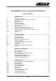
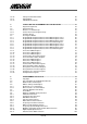
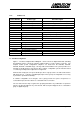
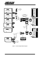
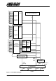
Table Of Contents
- INTRODUCTION
- GETTING STARTED
- MAKING THE CONNECTIONS
- USING THE PC215E
- STRUCTURE AND ASSIGNMENTS OF THE REGISTERS
- Register Assignments
- Register Groups
- The Register Details
- Programmable Peripheral Interface PPI-X Data Register Port A
- Programmable Peripheral Interface PPI-X Data Register Port B
- Programmable Peripheral Interface PPI-X Data Register Port C
- Programmable Peripheral Interface PPI-X Command Register
- Programmable Peripheral Interface PPI-Y Data Register Port A
- Programmable Peripheral Interface PPI-Y Data Register Port B
- Programmable Peripheral Interface PPI-Y Data Register Port C
- Programmable Peripheral Interface PPI-Y Command Register
- Z1 Counter 0 Data Register
- Z1 Counter 1 Data Register
- Z1 Counter 2 Data Register
- Counter/Timer Z1 Control Register
- Z1 Counter/Timer Status Register
- Z2 Counter 0 Data Register
- Z2 Counter 1 Data Register
- Z2 Counter 2 Data Register
- Counter/Timer Z2 Control Register
- Z2 Counter/Timer Status Register
- Group Z Clock Connection Register
- Group Z Gate Connection Register
- Interrupt Source Selection Register
- Interrupt Status Register
- PROGRAMMING THE PC215E
- Copyright
- Files installed from the Distribution Diskette
- Windows DLL and Examples
- DOS 'C' Library and Examples
- Using the Dynamic Link Library
- Windows and DOS Library Functions
- Initialisation Functions
- Interrupt Control Functions
- Data Buffer Functions
- Timer/Counter Functions
- Differential Counter Functions
- Frequency Generation Functions
- Millisecond Stopwatch Functions
- Frequency Input and Output Functions
- Digitally- and Voltage-Controlled Oscillator Functions
- Digital Input/Output Functions
- Switch Scanner Matrix Functions
- Bi-Directional Data Bus Functions
- PC215E Library Error Codes
- PC215E Interface Guide For LABTECH NOTEBOOK
- Guide to User Programming
- Signal Centre
- CONTENTS
- DECLARATION OF CONFORMITY

Page
1
PC215E
1. INTRODUCTION
1.1 The Amplicon 200 Series
The Amplicon 200 Series of Personal Computer based data acquisition products provides very
high performance, affordable hardware with comprehensive software support. The 200 Series is
designed for users requiring fast or complex data input/output to the host PC and comprises a
range of boards and software to handle most analog and digital signal types.
When a large scale system is required, multiple boards can be added from the 200 Series
without conflict. The capacity of the PC mounted hardware can be extended by external
expansion panels to provide a comprehensive system with low cost per channel and maintained
high performance.
1.2 The 200 Series Digital I/O Counter/Timer Family
The family of 200 Series digital input/output products may be configured in a variety of ways to
provide flexible, expansible systems.
Five digital input/output boards with timer/counter facilities are offered. These five boards are
complemented by four external panels for signal conditioning and user connection through
individual terminals. Support and demonstration software for all variants is offered.
A full, itemised list of hardware products is shown below, and a configurator diagram showing
how these products interact is also given. To complete the family, a common software package
supports all digital I/O boards and the expansion panels.
1.2.1 Typical Applications
• TTL compatible digital input/output
• Relay output with isolated contacts, high level ground referenced source drivers (any
combination)
• Isolated high or low level digital input, ground referenced high or low level digital input (any
combination)
• Interrogation of contact closure matrix - up to 1296 points per PC272E
• Elapsed time, period, frequency measurement
• Differential, ratiometric count
• Monostable and astable generation
• Frequency division, frequency multiplication, digitally controlled oscillator
• Voltage controlled oscillator (in conjunction with PC226E, PC30AT, PC26AT or PC27E)