
Instruction manual
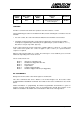

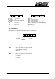
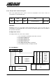


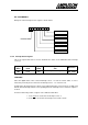


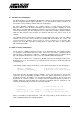
Table Of Contents
- INTRODUCTION
- GETTING STARTED
- MAKING THE CONNECTIONS
- USING THE PC215E
- STRUCTURE AND ASSIGNMENTS OF THE REGISTERS
- Register Assignments
- Register Groups
- The Register Details
- Programmable Peripheral Interface PPI-X Data Register Port A
- Programmable Peripheral Interface PPI-X Data Register Port B
- Programmable Peripheral Interface PPI-X Data Register Port C
- Programmable Peripheral Interface PPI-X Command Register
- Programmable Peripheral Interface PPI-Y Data Register Port A
- Programmable Peripheral Interface PPI-Y Data Register Port B
- Programmable Peripheral Interface PPI-Y Data Register Port C
- Programmable Peripheral Interface PPI-Y Command Register
- Z1 Counter 0 Data Register
- Z1 Counter 1 Data Register
- Z1 Counter 2 Data Register
- Counter/Timer Z1 Control Register
- Z1 Counter/Timer Status Register
- Z2 Counter 0 Data Register
- Z2 Counter 1 Data Register
- Z2 Counter 2 Data Register
- Counter/Timer Z2 Control Register
- Z2 Counter/Timer Status Register
- Group Z Clock Connection Register
- Group Z Gate Connection Register
- Interrupt Source Selection Register
- Interrupt Status Register
- PROGRAMMING THE PC215E
- Copyright
- Files installed from the Distribution Diskette
- Windows DLL and Examples
- DOS 'C' Library and Examples
- Using the Dynamic Link Library
- Windows and DOS Library Functions
- Initialisation Functions
- Interrupt Control Functions
- Data Buffer Functions
- Timer/Counter Functions
- Differential Counter Functions
- Frequency Generation Functions
- Millisecond Stopwatch Functions
- Frequency Input and Output Functions
- Digitally- and Voltage-Controlled Oscillator Functions
- Digital Input/Output Functions
- Switch Scanner Matrix Functions
- Bi-Directional Data Bus Functions
- PC215E Library Error Codes
- PC215E Interface Guide For LABTECH NOTEBOOK
- Guide to User Programming
- Signal Centre
- CONTENTS
- DECLARATION OF CONFORMITY
PC215E Page 52
BIT ASSIGNMENTS
Bit layouts of the Interrupt Source register is shown below.
5.3.22 Interrupt Status Register
This is the register that can be used to determine the status of the PC215E board’s interrupt
source(s).
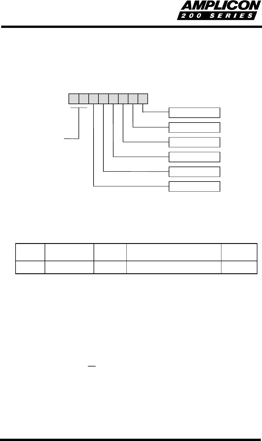
Register
Offset
Write and/or
Read
Register
Width
Register
Title
Mnemonic
1E
16
Read 8 bits
Interrupt Status Register
INT_STAT
FUNCTION
Gives the digital status of the selected interrupt sources. In order to read its status, a source
must have previously been selected as an interrupt source - see section 5.3.19.
A high level in the bit position of a given source indicates that the source has been set high, and
this bit will remain high until the corresponding bit in the Interrupt Source Selection register is
cleared.
A low level in the bit position of a given source indicates that either
1. it has not been selected as an interrupt source, or
2. it has been selected as an interrupt source and is set low.
01234567
PPI X Port C bit 0
PPI X Port C bit 3
PPI Y Port C bit 0
PPI Y Port C bit 3
Z1 OUT1
Z2 OUT1
reserved