
Instruction manual
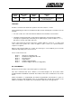

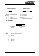
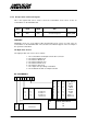


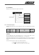


Table Of Contents
- INTRODUCTION
- GETTING STARTED
- MAKING THE CONNECTIONS
- USING THE PC215E
- STRUCTURE AND ASSIGNMENTS OF THE REGISTERS
- Register Assignments
- Register Groups
- The Register Details
- Programmable Peripheral Interface PPI-X Data Register Port A
- Programmable Peripheral Interface PPI-X Data Register Port B
- Programmable Peripheral Interface PPI-X Data Register Port C
- Programmable Peripheral Interface PPI-X Command Register
- Programmable Peripheral Interface PPI-Y Data Register Port A
- Programmable Peripheral Interface PPI-Y Data Register Port B
- Programmable Peripheral Interface PPI-Y Data Register Port C
- Programmable Peripheral Interface PPI-Y Command Register
- Z1 Counter 0 Data Register
- Z1 Counter 1 Data Register
- Z1 Counter 2 Data Register
- Counter/Timer Z1 Control Register
- Z1 Counter/Timer Status Register
- Z2 Counter 0 Data Register
- Z2 Counter 1 Data Register
- Z2 Counter 2 Data Register
- Counter/Timer Z2 Control Register
- Z2 Counter/Timer Status Register
- Group Z Clock Connection Register
- Group Z Gate Connection Register
- Interrupt Source Selection Register
- Interrupt Status Register
- PROGRAMMING THE PC215E
- Copyright
- Files installed from the Distribution Diskette
- Windows DLL and Examples
- DOS 'C' Library and Examples
- Using the Dynamic Link Library
- Windows and DOS Library Functions
- Initialisation Functions
- Interrupt Control Functions
- Data Buffer Functions
- Timer/Counter Functions
- Differential Counter Functions
- Frequency Generation Functions
- Millisecond Stopwatch Functions
- Frequency Input and Output Functions
- Digitally- and Voltage-Controlled Oscillator Functions
- Digital Input/Output Functions
- Switch Scanner Matrix Functions
- Bi-Directional Data Bus Functions
- PC215E Library Error Codes
- PC215E Interface Guide For LABTECH NOTEBOOK
- Guide to User Programming
- Signal Centre
- CONTENTS
- DECLARATION OF CONFORMITY

PC215E Page 46
Register
Offset
Write and/or
Read
Register
Width
Register
Title
Mnemonic
17
16
Write 8 bits
82C54 Z2 Counter/Timer
Control Register
Z2 CTC
FUNCTION
Provides a control word to define the operation of the Z2 counters 0, 1 and 2.
The programming procedure for the 82C54 is flexible, but the following two conventions must be
followed:
• For each counter, the control word must be written before the initial count is loaded.
• The initial count must follow the count format specified in the control word. This format is
normally least significant byte followed by most significant byte (control word bits 5, 4 = 1 1)
but can be L.S. byte only or M.S. byte only.
As the control register and each counter have separate addresses (offsets 0, 1, 2 and 3) and
each control word specifies the counter it applies to (bits 6 and 7) no special instruction
sequence is required.
When a control word is written to a counter, all control logic is reset and OUT goes to a known
initial state depending on the mode selected.
The six counter modes are:
Mode 0 Interrupt on Terminal Count
Mode 1 Hardware Re-triggerable One-shot
Mode 2 Rate Generator
Mode 3 Square Wave
Mode 4 Software Triggered Mode
Mode 5 Hardware Triggered Strobe (Re-triggerable)
BIT ASSIGNMENTS
Bit layout of the Z2 counter control word register is shown below.
Two other commands that can be written to the Control Register are the Counter Latch
Command and the Read-Back Command. The formats for these two commands are also shown
below.
Further information on programming the 82C54 Programmable Counter/Timer is given in
chapters 4 and 6. A full description of the six operating modes and all other features of the
82C54 are available in the 82C54 device manufacturer's data sheet in the appendices.