
Instruction manual

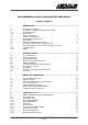
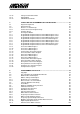
Table Of Contents
- INTRODUCTION
- GETTING STARTED
- MAKING THE CONNECTIONS
- USING THE PC215E
- STRUCTURE AND ASSIGNMENTS OF THE REGISTERS
- Register Assignments
- Register Groups
- The Register Details
- Programmable Peripheral Interface PPI-X Data Register Port A
- Programmable Peripheral Interface PPI-X Data Register Port B
- Programmable Peripheral Interface PPI-X Data Register Port C
- Programmable Peripheral Interface PPI-X Command Register
- Programmable Peripheral Interface PPI-Y Data Register Port A
- Programmable Peripheral Interface PPI-Y Data Register Port B
- Programmable Peripheral Interface PPI-Y Data Register Port C
- Programmable Peripheral Interface PPI-Y Command Register
- Z1 Counter 0 Data Register
- Z1 Counter 1 Data Register
- Z1 Counter 2 Data Register
- Counter/Timer Z1 Control Register
- Z1 Counter/Timer Status Register
- Z2 Counter 0 Data Register
- Z2 Counter 1 Data Register
- Z2 Counter 2 Data Register
- Counter/Timer Z2 Control Register
- Z2 Counter/Timer Status Register
- Group Z Clock Connection Register
- Group Z Gate Connection Register
- Interrupt Source Selection Register
- Interrupt Status Register
- PROGRAMMING THE PC215E
- Copyright
- Files installed from the Distribution Diskette
- Windows DLL and Examples
- DOS 'C' Library and Examples
- Using the Dynamic Link Library
- Windows and DOS Library Functions
- Initialisation Functions
- Interrupt Control Functions
- Data Buffer Functions
- Timer/Counter Functions
- Differential Counter Functions
- Frequency Generation Functions
- Millisecond Stopwatch Functions
- Frequency Input and Output Functions
- Digitally- and Voltage-Controlled Oscillator Functions
- Digital Input/Output Functions
- Switch Scanner Matrix Functions
- Bi-Directional Data Bus Functions
- PC215E Library Error Codes
- PC215E Interface Guide For LABTECH NOTEBOOK
- Guide to User Programming
- Signal Centre
- CONTENTS
- DECLARATION OF CONFORMITY

PC215E
PROGRAMMABLE DIGITAL I/O AND COUNTER/TIMER BOARD
TABLE OF CONTENTS
1. INTRODUCTION.......................................................................................................1
1.1 The Amplicon 200 Series 1
1.2 The 200 Series Digital I/O Counter/Timer Family 1
1.2.1 Typical Applications 1
1.2.2 Product List 2
1.3 Product Configurator 2
1.4 Features of the PC215E 4
1.5 PC215E General Description 4
1.5.1 The Software 4
1.6 What the PC215E Package Contains 6
1.7 The Amplicon Warranty Covering the PC215E 6
1.8 Contacting Amplicon Liveline Limited for Support or Service 7
1.8.1 Technical Support 7
1.8.2 Repairs 7
2. GETTING STARTED.................................................................................................8
2.1 General Information 8
2.2 Installing the Board 8
2.3 System Requirements 8
2.4 Backing up the Software Diskettes 8
2.5 Software Installation 9
2.6 Configuration Switch and Jumper Settings 9
2.6.1 Base Address Selection 9
2.6.2 PC I/O Map 10
2.6.3 Selection of Interrupt Request (IRQ) Level 10
2.7 Test Points 11
3. MAKING THE CONNECTIONS..............................................................................12
3.1 The Input/Output Connector 12
3.2 Cable Connections 13
3.2.1 Features Summary of the Expansion Panels 13
3.3 Use of Shielded Cables 14
3.4 Digital Input/Output Conditions 14
3.5 Counter/Timer Input/Output Conditions 14
3.6 PC Back-plane Bus Connections 14
4. USING THE PC215E...............................................................................................16
4.1 Multiple PC215E Boards in a Single Application 16
4.2 User Applications 16
4.2.1 Differential Counter 17
4.2.2 Monostable Multivibrator 17
4.2.3 Astable Multivibrator 17
4.2.4 Stopwatch 18
4.2.5 Event Recorder 18
4.2.6 Frequency/Period Measurement 19
4.2.7 Frequency Generation 19
4.2.8 Frequency Multiplication 19
4.2.9 Digitally Controlled Oscillator 19