
Instruction manual

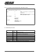


Table Of Contents
- INTRODUCTION
- GETTING STARTED
- MAKING THE CONNECTIONS
- USING THE PC215E
- STRUCTURE AND ASSIGNMENTS OF THE REGISTERS
- Register Assignments
- Register Groups
- The Register Details
- Programmable Peripheral Interface PPI-X Data Register Port A
- Programmable Peripheral Interface PPI-X Data Register Port B
- Programmable Peripheral Interface PPI-X Data Register Port C
- Programmable Peripheral Interface PPI-X Command Register
- Programmable Peripheral Interface PPI-Y Data Register Port A
- Programmable Peripheral Interface PPI-Y Data Register Port B
- Programmable Peripheral Interface PPI-Y Data Register Port C
- Programmable Peripheral Interface PPI-Y Command Register
- Z1 Counter 0 Data Register
- Z1 Counter 1 Data Register
- Z1 Counter 2 Data Register
- Counter/Timer Z1 Control Register
- Z1 Counter/Timer Status Register
- Z2 Counter 0 Data Register
- Z2 Counter 1 Data Register
- Z2 Counter 2 Data Register
- Counter/Timer Z2 Control Register
- Z2 Counter/Timer Status Register
- Group Z Clock Connection Register
- Group Z Gate Connection Register
- Interrupt Source Selection Register
- Interrupt Status Register
- PROGRAMMING THE PC215E
- Copyright
- Files installed from the Distribution Diskette
- Windows DLL and Examples
- DOS 'C' Library and Examples
- Using the Dynamic Link Library
- Windows and DOS Library Functions
- Initialisation Functions
- Interrupt Control Functions
- Data Buffer Functions
- Timer/Counter Functions
- Differential Counter Functions
- Frequency Generation Functions
- Millisecond Stopwatch Functions
- Frequency Input and Output Functions
- Digitally- and Voltage-Controlled Oscillator Functions
- Digital Input/Output Functions
- Switch Scanner Matrix Functions
- Bi-Directional Data Bus Functions
- PC215E Library Error Codes
- PC215E Interface Guide For LABTECH NOTEBOOK
- Guide to User Programming
- Signal Centre
- CONTENTS
- DECLARATION OF CONFORMITY

Page
111
PC215E
APPENDICES
APPENDIX A - GLOSSARY OF TERMS
The following glossary explains some terms used in this manual and in data acquisition and control applications.
Active Filter: An electronic filter that combines active circuit devices with passive circuit elements such as
resistors and capacitors. Active filters typically have characteristics that closely match ideal filters.
ADC (A/D): Analog to Digital converter. q.v.
Alias Frequency: A false lower frequency component that appears in analog signal reconstructed from original
data acquired at an insufficient sampling rate.
Algorithm: A set of rules, with a finite number of steps, for solving a mathematical problem. An algorithm can be
used as a basis for a computer program.
Analog to Digital Converter (ADC): A device for converting an analog voltage to a parallel digital word where the
digital output code represents the magnitude of the input signal. See ‘Successive Approximation’.
Analog Switch: An electronic, single pole, two way switch capable of handling the full range of analog signal
voltage, and operating under the control of a logic signal.
Array: Data arranged in single or multidimensional rows and columns.
ASCII: American Standard Code for Information Interchange. A code that is commonly used to represent symbols
in computers.
Assembler: A program that converts a list of computer instructions written in a specific assembly language format
that can be executed by a specific processor.
Bandpass Filter: A type of electrical filter that allows a band of signals between two set frequencies to pass,
while attenuating all signal frequencies outside the bandpass range.
Base Address: A unique address set up on an I/O card to allow reference by the host computer. All registers are
located by an offset in relation to the base address.
BASIC: The most common computer language. BASIC is an acronym for Beginners All-purpose Symbolic
Instruction Code. BASIC is not rigorously structured and relies on English-like instructions which account for its
popularity.
Binary Coded Decimal (BCD): A system of binary numbering where each decimal digit 0 through 9 is
represented by a combination of four bits.
BIOS: Basic Input Output System. BIOS resides in ROM on a computer system board and provides device level
control for the major I/O devices on the system.
Bipolar: A signal being measured is said to be bipolar when the voltage on its 'high' terminal can be either of
positive or negative polarity in relation to its 'low' terminal.
Bit: Contraction of binary digit. The smallest unit of information. A bit represents the choice between a one or zero
value (mark or space in communications technology).
Buffer: A storage device used to compensate for a difference in rate of data flow, or time of occurrence of events,
when transferring data from one device to another. Also a device without storage that isolates two circuits.
Bus: Conductors used to interconnect individual circuitry in a computer. The set of conductors as a whole is
called a bus.
Byte: A binary element string operated on as a unit and usually shorter than a computer word. Normally eight bits.
C: A high level programming language, developed around the concept of structured programming and designed
for high operating speeds. Microsoft 'C' and Turbo 'C' are dialects of C.
Channel: One of several signal/data paths that may be selected.
Character: A letter, figure , number, punctuation or other symbol contained in a message or used in a control
function.
Code: A set of unambiguous rules specifying the way in which characters may be represented.
Conversion Time: The time required for a complete conversion of a value from analog to digital form (ADC) or
analog to digital form (DAC). Inverse of Conversion Rate.
Cold Junction: See Thermocouple Reference Junction
Cold Junction Compensation (CJC): A technique to compensate for thermocouple measurement offset when
the reference or cold junction is at a temperature other than 0° C.