
Instruction manual

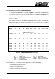


Table Of Contents
- INTRODUCTION
- GETTING STARTED
- MAKING THE CONNECTIONS
- USING THE PC215E
- STRUCTURE AND ASSIGNMENTS OF THE REGISTERS
- Register Assignments
- Register Groups
- The Register Details
- Programmable Peripheral Interface PPI-X Data Register Port A
- Programmable Peripheral Interface PPI-X Data Register Port B
- Programmable Peripheral Interface PPI-X Data Register Port C
- Programmable Peripheral Interface PPI-X Command Register
- Programmable Peripheral Interface PPI-Y Data Register Port A
- Programmable Peripheral Interface PPI-Y Data Register Port B
- Programmable Peripheral Interface PPI-Y Data Register Port C
- Programmable Peripheral Interface PPI-Y Command Register
- Z1 Counter 0 Data Register
- Z1 Counter 1 Data Register
- Z1 Counter 2 Data Register
- Counter/Timer Z1 Control Register
- Z1 Counter/Timer Status Register
- Z2 Counter 0 Data Register
- Z2 Counter 1 Data Register
- Z2 Counter 2 Data Register
- Counter/Timer Z2 Control Register
- Z2 Counter/Timer Status Register
- Group Z Clock Connection Register
- Group Z Gate Connection Register
- Interrupt Source Selection Register
- Interrupt Status Register
- PROGRAMMING THE PC215E
- Copyright
- Files installed from the Distribution Diskette
- Windows DLL and Examples
- DOS 'C' Library and Examples
- Using the Dynamic Link Library
- Windows and DOS Library Functions
- Initialisation Functions
- Interrupt Control Functions
- Data Buffer Functions
- Timer/Counter Functions
- Differential Counter Functions
- Frequency Generation Functions
- Millisecond Stopwatch Functions
- Frequency Input and Output Functions
- Digitally- and Voltage-Controlled Oscillator Functions
- Digital Input/Output Functions
- Switch Scanner Matrix Functions
- Bi-Directional Data Bus Functions
- PC215E Library Error Codes
- PC215E Interface Guide For LABTECH NOTEBOOK
- Guide to User Programming
- Signal Centre
- CONTENTS
- DECLARATION OF CONFORMITY

Page
109
PC215E
6.8.1 Channel Assignments:
Digital Input/Output channels:
Channel 0 PPIX Port A
Channel 1 PPIX Port B
Channel 2 PPIX Port C
Channel 3 PPIY Port A
Channel 4 PPIY Port B
Channel 5 PPIY Port C
Frequency Output channel:
Channel 0 Z1 Counter 2
Channel 1 Z2 Counter 2
Counter Input channel:
Channel 0 Z1 Counter 0
Channel 1 Z2 Counter 0
Frequency Measurement channel:
Channel 0 Z1 Counter 0
Channel 1 Z2 Counter 0
6.8.2 Configuring the Board
The following connections are required to set the board up for the supported LABTECH NOTEBOOK
channel types:
Frequency Output channels:
Frequency output available on Counter 2 OUT
Counter Input channels:
Connect the input signal to Counter 0 CLOCK
Frequency Measurement channels:
Connect the input signal to Counter 0 CLOCK