
Instruction manual

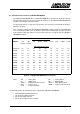


Table Of Contents
- INTRODUCTION
- GETTING STARTED
- MAKING THE CONNECTIONS
- USING THE PC215E
- STRUCTURE AND ASSIGNMENTS OF THE REGISTERS
- Register Assignments
- Register Groups
- The Register Details
- Programmable Peripheral Interface PPI-X Data Register Port A
- Programmable Peripheral Interface PPI-X Data Register Port B
- Programmable Peripheral Interface PPI-X Data Register Port C
- Programmable Peripheral Interface PPI-X Command Register
- Programmable Peripheral Interface PPI-Y Data Register Port A
- Programmable Peripheral Interface PPI-Y Data Register Port B
- Programmable Peripheral Interface PPI-Y Data Register Port C
- Programmable Peripheral Interface PPI-Y Command Register
- Z1 Counter 0 Data Register
- Z1 Counter 1 Data Register
- Z1 Counter 2 Data Register
- Counter/Timer Z1 Control Register
- Z1 Counter/Timer Status Register
- Z2 Counter 0 Data Register
- Z2 Counter 1 Data Register
- Z2 Counter 2 Data Register
- Counter/Timer Z2 Control Register
- Z2 Counter/Timer Status Register
- Group Z Clock Connection Register
- Group Z Gate Connection Register
- Interrupt Source Selection Register
- Interrupt Status Register
- PROGRAMMING THE PC215E
- Copyright
- Files installed from the Distribution Diskette
- Windows DLL and Examples
- DOS 'C' Library and Examples
- Using the Dynamic Link Library
- Windows and DOS Library Functions
- Initialisation Functions
- Interrupt Control Functions
- Data Buffer Functions
- Timer/Counter Functions
- Differential Counter Functions
- Frequency Generation Functions
- Millisecond Stopwatch Functions
- Frequency Input and Output Functions
- Digitally- and Voltage-Controlled Oscillator Functions
- Digital Input/Output Functions
- Switch Scanner Matrix Functions
- Bi-Directional Data Bus Functions
- PC215E Library Error Codes
- PC215E Interface Guide For LABTECH NOTEBOOK
- Guide to User Programming
- Signal Centre
- CONTENTS
- DECLARATION OF CONFORMITY

PC215E Page 108
6.8 PC215E Interface Guide For LABTECH NOTEBOOK
The LABTECH NOTEBOOK drivers supplied by Amplicon on the PC215E distribution diskette
are specifically designed to interface the PC215E hardware to the LABTECH NOTEBOOK Data
Acquisition and Analysis software package.
The appropriate drivers to support the functionality of the board are provided with all Amplicon
200 Series products.
A list of I/O types supported by the LABTECH NOTEBOOK software, and their compatibility with
some of the Amplicon 200 series I/O boards is given in the following table. Functions provided
by the Amplicon I/O boards which are not listed in the table are not supported by the LABTECH
NOTEBOOK software.
LABTECH Software I/O Types
Module AD AD DA DI/DO TEMP STRN CNT FREQ PLSE
Normal Hi-Spd
AMPLICON Board Types
PC224/34 No No Yes No No No Yes Yes Yes
PC226 Yes Yes No Yes Yes No No No No
PC230 Yes Yes Yes Yes Yes No Yes Yes Yes
PC237 No No No Yes No No No No No
PC263 NoNoNoDONoNoNoNoNo
PC214E No No No Yes No No Yes Yes Yes
PC215E No No No Yes No No Yes Yes Yes
PC212E No No No Yes No No Yes Yes Yes
PC218E No No No No No No Yes Yes Yes
PC272E No No No Yes No No No No No
Figure 9 - LABTECH NOTEBOOK Driver Functions
where: AD = Analog Input DA = Analog Output
DI = Digital Input DO = Digital Output
TEMP = Temperature Measurement STRN = Strain Measurement
CNT = Counter Input FREQ = Frequency Measurement
PLSE = Frequency Output.
The PC215E provides the following I/O types supported by LABTECH NOTEBOOK:
• Six 8-bit Digital Input/Output channels
• Two Frequency Output channels
• Two Counter Input channels
• Two Frequency Measurement channels