
Instruction manual

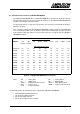


Table Of Contents
- INTRODUCTION
- GETTING STARTED
- MAKING THE CONNECTIONS
- USING THE PC215E
- STRUCTURE AND ASSIGNMENTS OF THE REGISTERS
- Register Assignments
- Register Groups
- The Register Details
- Programmable Peripheral Interface PPI-X Data Register Port A
- Programmable Peripheral Interface PPI-X Data Register Port B
- Programmable Peripheral Interface PPI-X Data Register Port C
- Programmable Peripheral Interface PPI-X Command Register
- Programmable Peripheral Interface PPI-Y Data Register Port A
- Programmable Peripheral Interface PPI-Y Data Register Port B
- Programmable Peripheral Interface PPI-Y Data Register Port C
- Programmable Peripheral Interface PPI-Y Command Register
- Z1 Counter 0 Data Register
- Z1 Counter 1 Data Register
- Z1 Counter 2 Data Register
- Counter/Timer Z1 Control Register
- Z1 Counter/Timer Status Register
- Z2 Counter 0 Data Register
- Z2 Counter 1 Data Register
- Z2 Counter 2 Data Register
- Counter/Timer Z2 Control Register
- Z2 Counter/Timer Status Register
- Group Z Clock Connection Register
- Group Z Gate Connection Register
- Interrupt Source Selection Register
- Interrupt Status Register
- PROGRAMMING THE PC215E
- Copyright
- Files installed from the Distribution Diskette
- Windows DLL and Examples
- DOS 'C' Library and Examples
- Using the Dynamic Link Library
- Windows and DOS Library Functions
- Initialisation Functions
- Interrupt Control Functions
- Data Buffer Functions
- Timer/Counter Functions
- Differential Counter Functions
- Frequency Generation Functions
- Millisecond Stopwatch Functions
- Frequency Input and Output Functions
- Digitally- and Voltage-Controlled Oscillator Functions
- Digital Input/Output Functions
- Switch Scanner Matrix Functions
- Bi-Directional Data Bus Functions
- PC215E Library Error Codes
- PC215E Interface Guide For LABTECH NOTEBOOK
- Guide to User Programming
- Signal Centre
- CONTENTS
- DECLARATION OF CONFORMITY

PC215E Page 106
6.6.12 Bi-Directional Data Bus Functions
6.6.12.1 Prepare an 8-bit Bi-Directional Data Bus - DIOsetBiDirectionalBus
Programs Group A of a DIO chip for Mode 2 ‘Strobe bi-directional bus I/O operation’. Group B
(Port B and Port C-lower) are not used in the bi-directional bus, and are programmed by this
function for Mode 0 input or output as specified in the isPBip and isPCLip arguments. They
can be accessed in the normal way using the DIOsetData and DIOgetData functions. Up to
three bi-directional buses are available per board (if PPIs are available). See section 4.2.12 for
more details on the Bi-directional Bus application.
i = DIOsetBiDirectionalBus (h, chip, isPBip, isPCLip, bIn, bOut)
where
h Integer. Board handle as issued by function
registerBoard.
chip Integer. Address offset of the DIO chip. Use
one of the following pre-defined constants:-
PPIX = 0
PPIY = 8
PPIZ = 16
isPBip Integer. Non-zero if Port B is to be set as input,
zero if output.
isPCLip Integer. Non-zero if Port C-lower are to be set
as input, zero if output.
bIn Integer. Handle to a buffer previously allocated
as 2-bytes per item by the allocateBuf function.
This buffer will be used to store incoming digital
input data from the bus.
bOut Integer. Handle to a buffer previously allocated
as 2-bytes per item by the allocateBuf function.
This buffer should contain digital output data to
be send out onto the bus upon request.
Returns Integer:
Positive handle to the bi-directional bus. Use this handle in the call
to DIOfreeBiDirectionalBus when finished, to free the DIO
resources.
or ERRHANDLE
ERRCHAN
ERRBUFFER
Prior Calls registerBoard
See Also enableInterrupts
DIOfreeBiDirectionalBus