
Instruction manual


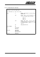
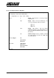

Table Of Contents
- INTRODUCTION
- GETTING STARTED
- MAKING THE CONNECTIONS
- USING THE PC215E
- STRUCTURE AND ASSIGNMENTS OF THE REGISTERS
- Register Assignments
- Register Groups
- The Register Details
- Programmable Peripheral Interface PPI-X Data Register Port A
- Programmable Peripheral Interface PPI-X Data Register Port B
- Programmable Peripheral Interface PPI-X Data Register Port C
- Programmable Peripheral Interface PPI-X Command Register
- Programmable Peripheral Interface PPI-Y Data Register Port A
- Programmable Peripheral Interface PPI-Y Data Register Port B
- Programmable Peripheral Interface PPI-Y Data Register Port C
- Programmable Peripheral Interface PPI-Y Command Register
- Z1 Counter 0 Data Register
- Z1 Counter 1 Data Register
- Z1 Counter 2 Data Register
- Counter/Timer Z1 Control Register
- Z1 Counter/Timer Status Register
- Z2 Counter 0 Data Register
- Z2 Counter 1 Data Register
- Z2 Counter 2 Data Register
- Counter/Timer Z2 Control Register
- Z2 Counter/Timer Status Register
- Group Z Clock Connection Register
- Group Z Gate Connection Register
- Interrupt Source Selection Register
- Interrupt Status Register
- PROGRAMMING THE PC215E
- Copyright
- Files installed from the Distribution Diskette
- Windows DLL and Examples
- DOS 'C' Library and Examples
- Using the Dynamic Link Library
- Windows and DOS Library Functions
- Initialisation Functions
- Interrupt Control Functions
- Data Buffer Functions
- Timer/Counter Functions
- Differential Counter Functions
- Frequency Generation Functions
- Millisecond Stopwatch Functions
- Frequency Input and Output Functions
- Digitally- and Voltage-Controlled Oscillator Functions
- Digital Input/Output Functions
- Switch Scanner Matrix Functions
- Bi-Directional Data Bus Functions
- PC215E Library Error Codes
- PC215E Interface Guide For LABTECH NOTEBOOK
- Guide to User Programming
- Signal Centre
- CONTENTS
- DECLARATION OF CONFORMITY

PC215E Page 104
6.6.11 Switch Scanner Matrix Functions
6.6.11.1 Setup a Switch Scanner Matrix - DIOsetSwitchMatrix
Sets up one, two or three 82C55 DIO chips as a switch matrix scanning device. The order of
the matrix specified can be 12 (for a 12 X 12 matrix scanning 144 switches, using PPIX), 24
(for a 24 X 24 matrix scanning 576 switches, using PPIX and PPIY), or 36 (for a 36 X 36 matrix
scanning 1296 switches, using PPIX, PPIY and PPIZ). Group A (ports A and C-upper) are set
for output, to send test patterns to the matrix, and group B (port B and C-lower) are set for input
to read the switch status information back in. The user must ensure that the switch array is
wired correctly with suitable diodes and resistors, otherwise the board could get damaged.
See section 4.2.11 for details. Only one switch matrix implementation is available per board.
i = DIOsetSwitchMatrix (h, order)
where
h Integer. Board handle as issued by function
registerBoard.
order Integer. Order of the matrix (12, 24 or 36)
Returns Integer:
OK
or ERRHANDLE
ERRCHAN
Prior Calls registerBoard
See Also DIOgetSwitchStatus
DIOfreeSwitchMatrix