
Instruction manual


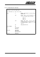
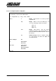

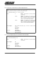
Table Of Contents
- INTRODUCTION
- GETTING STARTED
- MAKING THE CONNECTIONS
- USING THE PC215E
- STRUCTURE AND ASSIGNMENTS OF THE REGISTERS
- Register Assignments
- Register Groups
- The Register Details
- Programmable Peripheral Interface PPI-X Data Register Port A
- Programmable Peripheral Interface PPI-X Data Register Port B
- Programmable Peripheral Interface PPI-X Data Register Port C
- Programmable Peripheral Interface PPI-X Command Register
- Programmable Peripheral Interface PPI-Y Data Register Port A
- Programmable Peripheral Interface PPI-Y Data Register Port B
- Programmable Peripheral Interface PPI-Y Data Register Port C
- Programmable Peripheral Interface PPI-Y Command Register
- Z1 Counter 0 Data Register
- Z1 Counter 1 Data Register
- Z1 Counter 2 Data Register
- Counter/Timer Z1 Control Register
- Z1 Counter/Timer Status Register
- Z2 Counter 0 Data Register
- Z2 Counter 1 Data Register
- Z2 Counter 2 Data Register
- Counter/Timer Z2 Control Register
- Z2 Counter/Timer Status Register
- Group Z Clock Connection Register
- Group Z Gate Connection Register
- Interrupt Source Selection Register
- Interrupt Status Register
- PROGRAMMING THE PC215E
- Copyright
- Files installed from the Distribution Diskette
- Windows DLL and Examples
- DOS 'C' Library and Examples
- Using the Dynamic Link Library
- Windows and DOS Library Functions
- Initialisation Functions
- Interrupt Control Functions
- Data Buffer Functions
- Timer/Counter Functions
- Differential Counter Functions
- Frequency Generation Functions
- Millisecond Stopwatch Functions
- Frequency Input and Output Functions
- Digitally- and Voltage-Controlled Oscillator Functions
- Digital Input/Output Functions
- Switch Scanner Matrix Functions
- Bi-Directional Data Bus Functions
- PC215E Library Error Codes
- PC215E Interface Guide For LABTECH NOTEBOOK
- Guide to User Programming
- Signal Centre
- CONTENTS
- DECLARATION OF CONFORMITY

Page
101
PC215E
6.6.10.3 Re-define Channel Width within a Digital I/O Chip - DIOsetChanWidth
Redefines the number of bits per DIO channel to be used in subsequent calls to the
DIOsetData and DIOgetData functions. The default channel width is 8-bits, and this can be
changed to 1, 4, 8, 12, 16, or 24. After calling this function, the chan argument in the
DIOsetData and DIOgetData functions refers to the group of bits of width
numBits
, starting at
Port A bit 0. Note that the three ports (A, B, C-upper and C-lower) must be setup correctly for
input or output accordingly by calling the DIOsetMode function for each.
i = DIOsetChanWidth (h, chip, numBits)
where
h Integer. Board handle as issued by function
registerBoard.
chip Integer. Address offset of the DIO chip. Use
one of the following pre-defined constants:-
PPIX = 0
PPIY = 8
PPIZ = 16
numBits Integer. Bit width to be used in subsequent
calls to functions DIOsetData, DIOgetData and
TCsetDCO. Valid widths are 1, 4, 8, 12, 16, or
24.
numBits
1
4
8
12
16
24
channels per chip
24
6
3
2
1
1
Returns Integer: OK
or ERRHANDLE
ERRCHAN
ERRDATA
Prior Calls registerBoard
See Also DIOsetMode
DIOsetData
DIOgetData