
Instruction manual


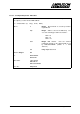
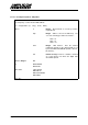

Table Of Contents
- INTRODUCTION
- GETTING STARTED
- MAKING THE CONNECTIONS
- USING THE PC215E
- STRUCTURE AND ASSIGNMENTS OF THE REGISTERS
- Register Assignments
- Register Groups
- The Register Details
- Programmable Peripheral Interface PPI-X Data Register Port A
- Programmable Peripheral Interface PPI-X Data Register Port B
- Programmable Peripheral Interface PPI-X Data Register Port C
- Programmable Peripheral Interface PPI-X Command Register
- Programmable Peripheral Interface PPI-Y Data Register Port A
- Programmable Peripheral Interface PPI-Y Data Register Port B
- Programmable Peripheral Interface PPI-Y Data Register Port C
- Programmable Peripheral Interface PPI-Y Command Register
- Z1 Counter 0 Data Register
- Z1 Counter 1 Data Register
- Z1 Counter 2 Data Register
- Counter/Timer Z1 Control Register
- Z1 Counter/Timer Status Register
- Z2 Counter 0 Data Register
- Z2 Counter 1 Data Register
- Z2 Counter 2 Data Register
- Counter/Timer Z2 Control Register
- Z2 Counter/Timer Status Register
- Group Z Clock Connection Register
- Group Z Gate Connection Register
- Interrupt Source Selection Register
- Interrupt Status Register
- PROGRAMMING THE PC215E
- Copyright
- Files installed from the Distribution Diskette
- Windows DLL and Examples
- DOS 'C' Library and Examples
- Using the Dynamic Link Library
- Windows and DOS Library Functions
- Initialisation Functions
- Interrupt Control Functions
- Data Buffer Functions
- Timer/Counter Functions
- Differential Counter Functions
- Frequency Generation Functions
- Millisecond Stopwatch Functions
- Frequency Input and Output Functions
- Digitally- and Voltage-Controlled Oscillator Functions
- Digital Input/Output Functions
- Switch Scanner Matrix Functions
- Bi-Directional Data Bus Functions
- PC215E Library Error Codes
- PC215E Interface Guide For LABTECH NOTEBOOK
- Guide to User Programming
- Signal Centre
- CONTENTS
- DECLARATION OF CONFORMITY
PC215E Page 98
the update ticks.
freq0V Float. Output frequency, in Hertz,
corresponding to 0.0 Volts on the analog input
channel.
freq10V Float. Output frequency, in Hertz,
corresponding to +10.0 Volts on the analog
input channel (or +4.0 Volts if using a PC27E).
Returns Integer:
Positive handle to VCO. Use this handle to call TCfreeDCO when
finished.
or ERRHANDLE
ERRCHAN
ERRDATA
ERRRANGE
ERRPC226
Prior Calls registerBoard
See Also TCsetDCO
enableInterrupts
TCfreeDCO
6.6.9.3 Free-up a DCO or VCO's Timer/Counters - TCfreeDCO
Frees the timer/counter & DIO resources used by a DCO, or VCO, as previously setup by
TCsetDCO or TCsetVCO. Call this function when you’ve finished using the DCO or VCO.
i = TCfreeDCO (h, hO)
where
h Integer. Board handle as issued by function
registerBoard.
hO Integer. DCO or VCO handle, as issued by
TCsetDCO or TCsetVCO, respectively.
Returns Integer:
OK
or ERRHANDLE
ERRCHAN
Prior Calls registerBoard
TCsetDCO
TCsetVCO
enableInterrupts
See Also disableInterrupts